|
|
|
The Mod:Add components and wiring to support auxiliary electrical devices. What it does:Without voiding your electrical warrantee, and possibly causing fires and/or serious injuries, new electrical components should not be wired directly to your existing Jeep wiring harness. All power for these devices should come directly from the battery. This page shows how the power for these devices is obtained, protected, and distributed to the auxiliary components. The heart of the system is a weather resistant Bussmann 15303-5-2-4 Rear Terminal Mini Fuse and Relay (RTMR) Panel. It supports a bussed connection to 10 mini fuses and 5 micro relays that can be connected as necessary to create circuits for your auxiliary components. Good automotive grade switches with automotive connectors should hold up well, and their connectors make it easy to work on and install the switches. All wiring should be made with automotive grade wires (not the cheap stuff you typically find in the stores). This page has lots of pictures of the assembly of the components. You can skip to the end to see the finished shots. References:Voltage Drop Calculator - used to estimate the wire size you need for a given load. You don't want to have more than a 3% voltage drop. Note that the length of the wire in the calculator is the one way distance, the calculator doubles this number for its calculations, so if you have a 10 foot run to a device and it goes directly to ground then you should enter 5 feet in the calculator. TXL Wire Source - good source for TXL wire and terminals. 301 Relays - I used the 301-1A-C-R1 sealed relays that have a built-in resistor. Terminal Installation - information for using and installing terminals. ANL Fuse Data Sheet - time vs. current for different fuse ratings. Outline:There are many sub-section on this page, so here is an outline you can use to jump to a specific section.
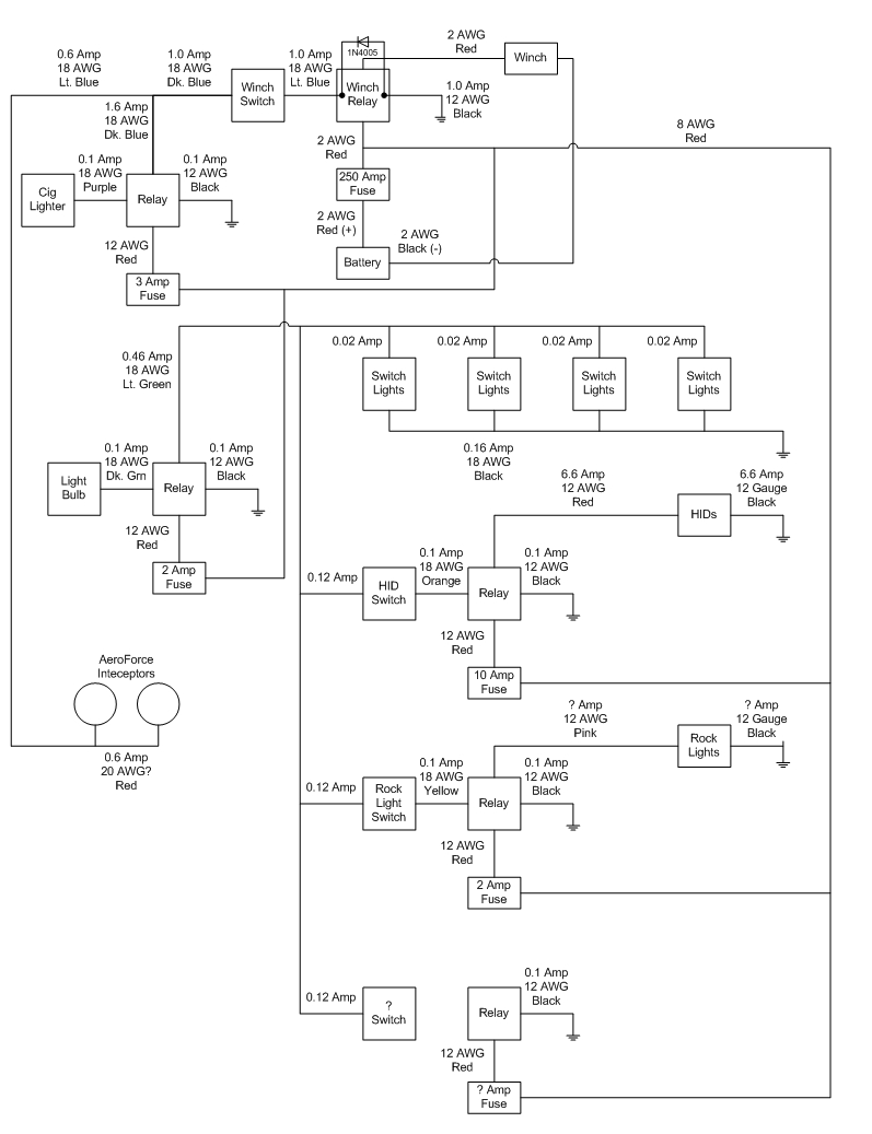
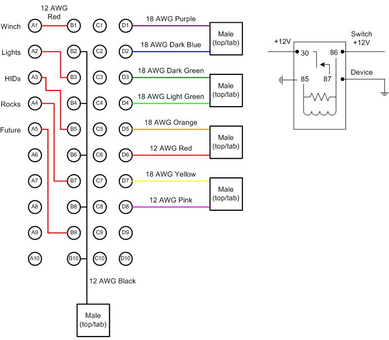
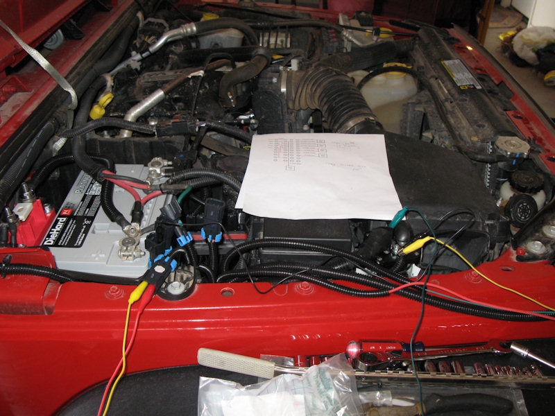
Photos:Wiring Diagram:Here's the wiring diagram. The last relay is unused, but partially wired. Also the last 5 fuses are not used yet:
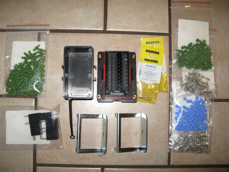
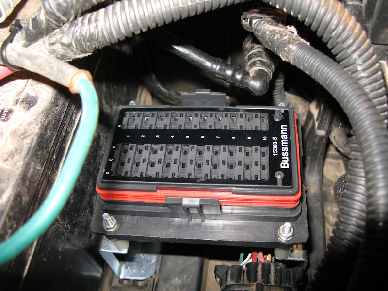
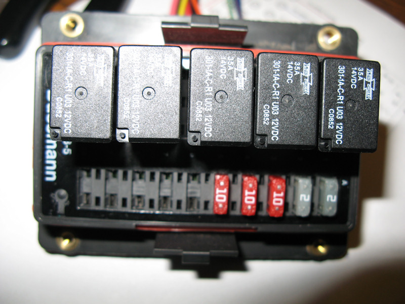
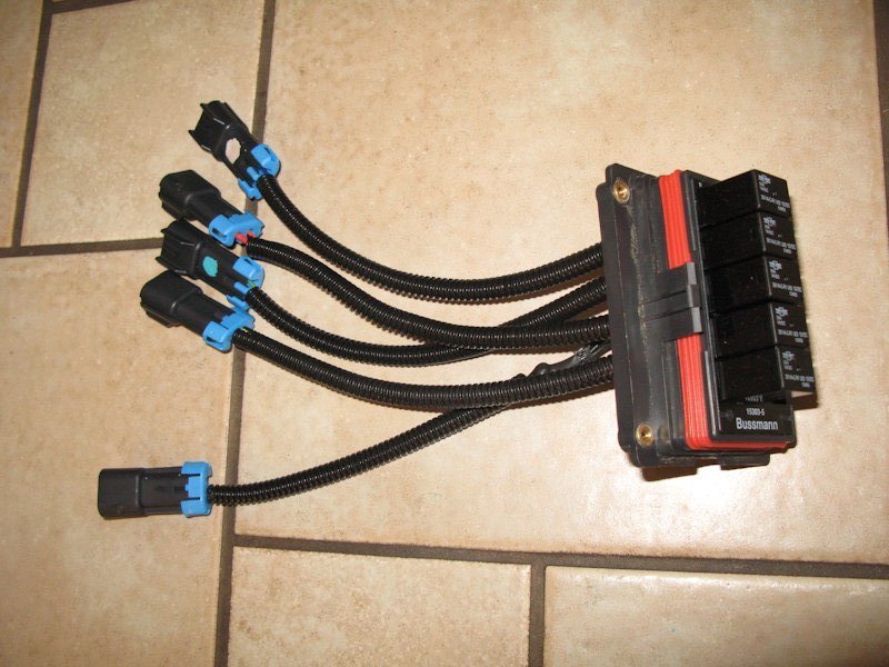
Components:The Bussmann RTMR Panel (center) has a weather tight cover and support legs, the terminal plugs that are inserted from the rear are also weather tight (right), and the empty holes are filled the the plugs on the left. Mini fuses are inserted to on the right side (none pictured), and relays are inserted in the left side (5 pictured in the bag in the lower left):
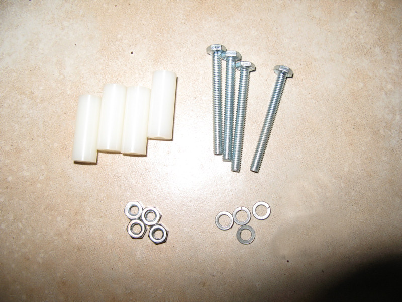
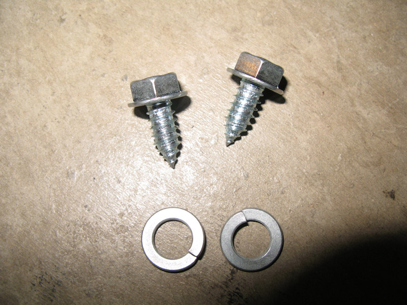
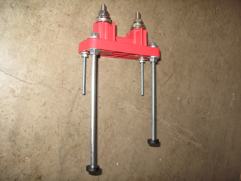
Some hardware I purchased to mount the RTMR Panel (note that I replaced the plastic standoff's with aluminum ones):
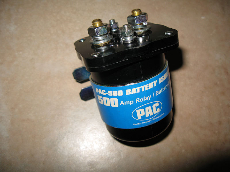
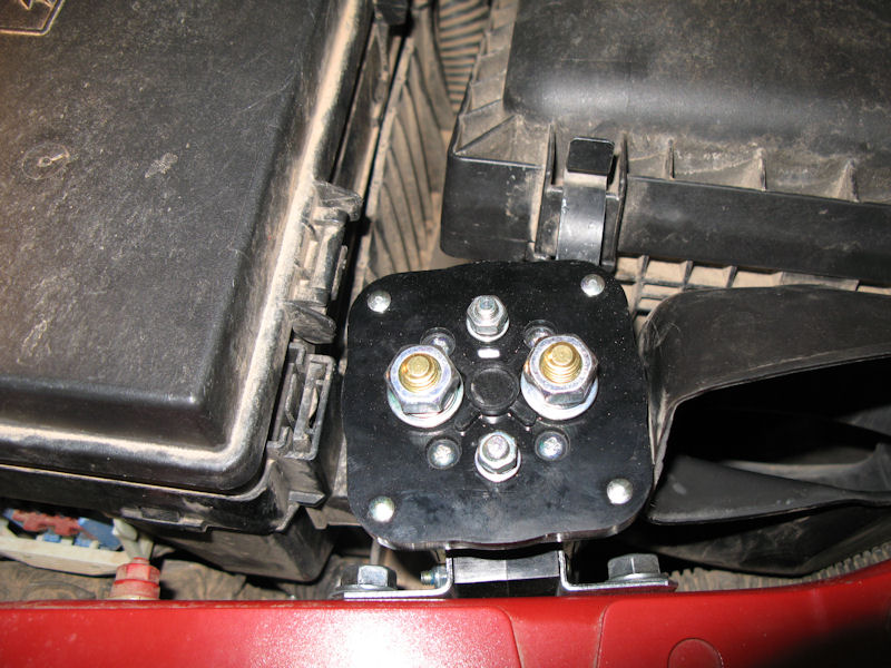
The winch is hard wired to the battery, so it's always "on". This 500 amp relay is used to switch the power to winch on only when the key is in the ignition and the winch switch is on. Warn sells a relay that is good to 175 Amps continuous, but the specification on the Winch says it can run up to 416 Amps when under max load, so I figured this 500 Amp continuous/700 Amp Peak Relay would be safer:
Some hardware I purchased to mount the relay:
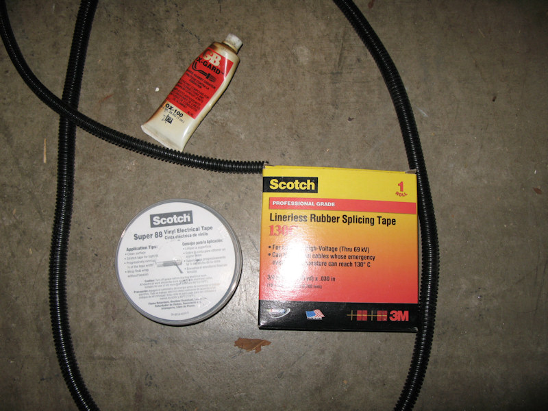
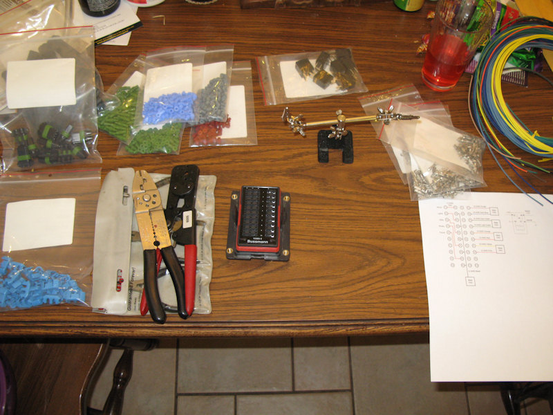
Some of the hookup parts and equipment. I ordered TXL wire for this job as it will be run under the hood. All of the different color wire cost more (because there's more scrap), but makes it makes for a clearer finished product:
Some more supplies - I really used lots of different size wire looms:
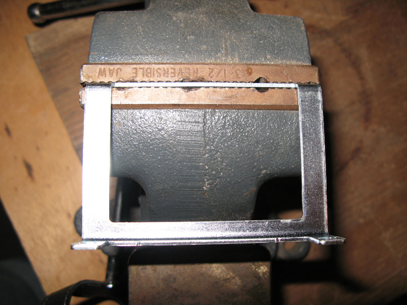
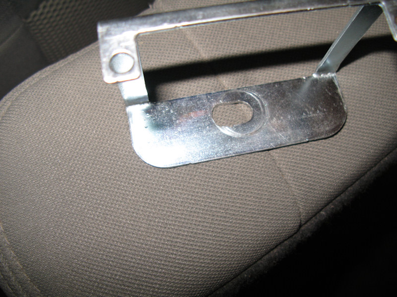
Bussmann RTMR Panel Installation:One of the brackets has to be modified. The bottom of it has to be bent 180°. Insert it in a vise:
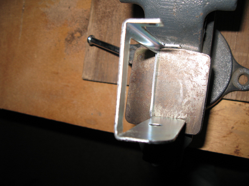
Bend and straighten with a hammer:
The hole has to be expanded a bit so it can be adjusted to fit properly:
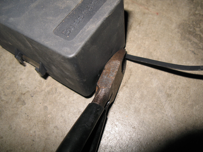
Cut off the tab on the lid:
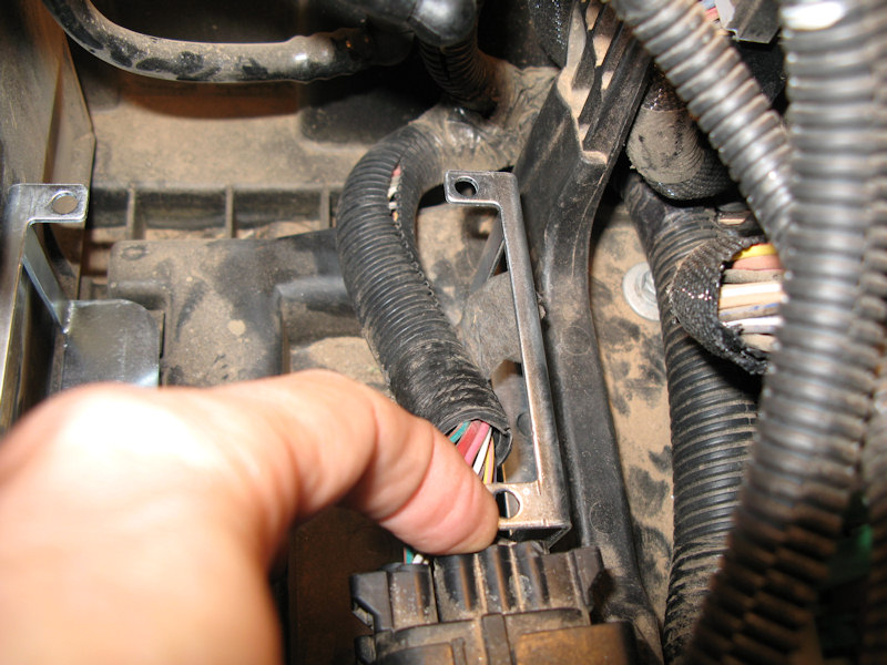
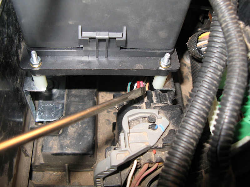
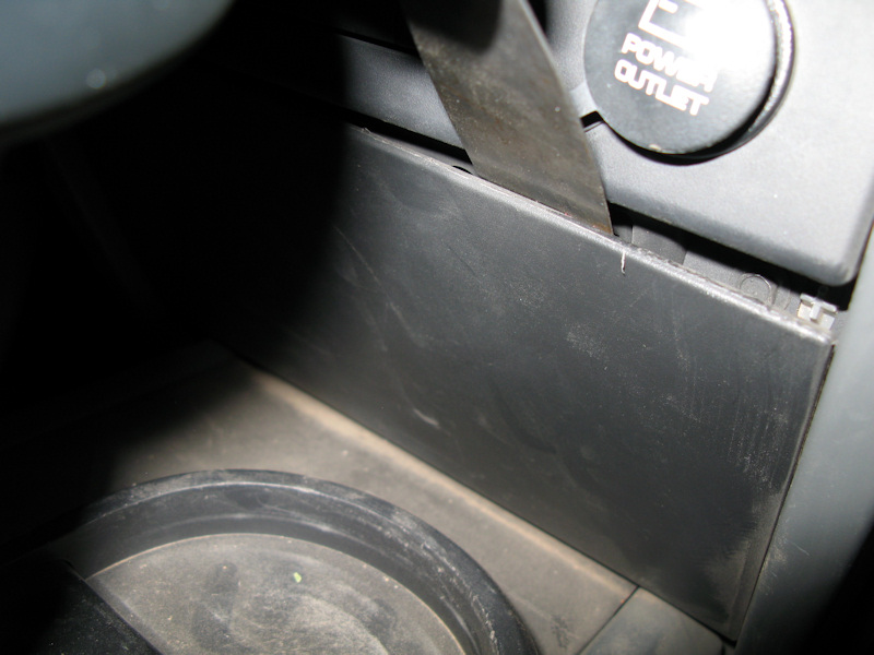
Loosely install the "bent" bracket using the battery hold down screw. The other bracket has to slide under the fuse block. If you click the 4 tabs and slide it out you can gain access to the bolts that hold it down. Loosen them and slide the bracket under it. You want to make sure the connector in the front does not touch the bracket:
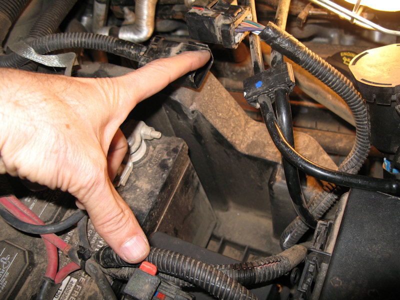
To install the RTMR bracket it helps to disconnect these two connectors:
Loosely insert the bolts into the bracket, with the standoff's. Make sure there is still clearance at the front brcaket:
And in the rear:
And at the battery:
When all clearances look good, you need to tighten the bolts under the fuse block which will hold down bracket the bracket closer to the front of the Jeep, and tighten down the bracket by the battery:
The top can come off:
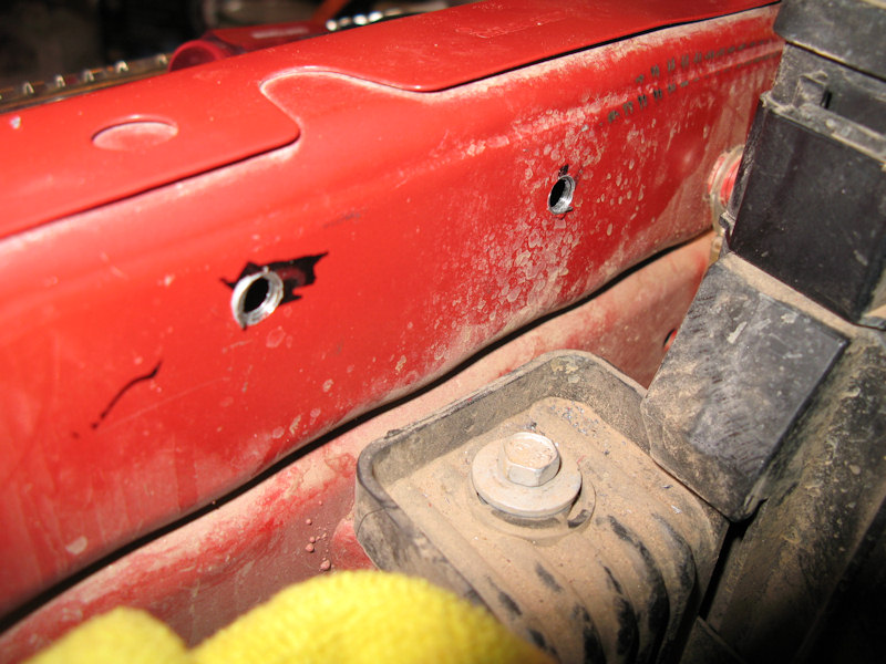
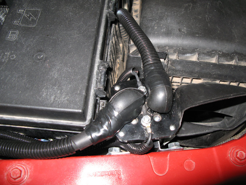
Winch Relay Installation:Move the air box back out of the way and drill to holes:
Secure the relay and move the air box back in place:
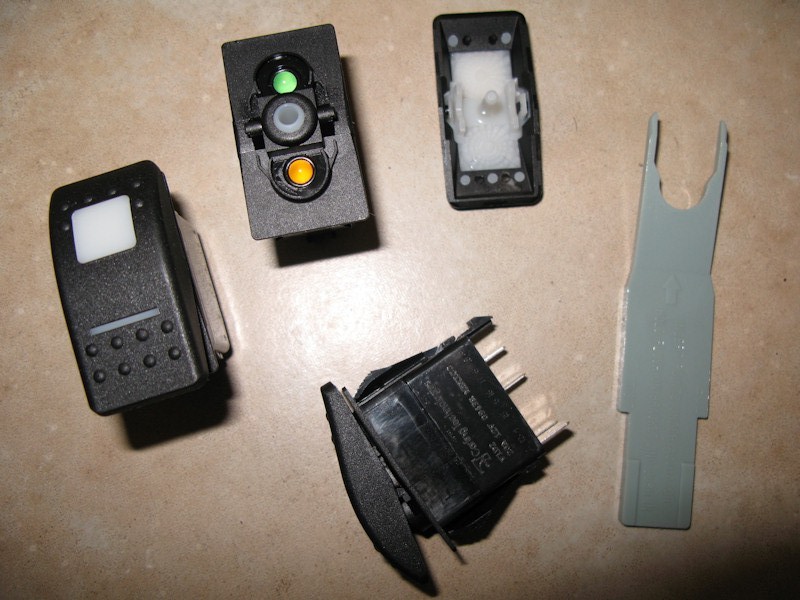
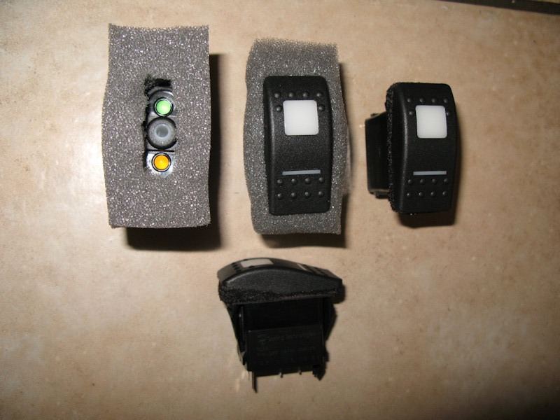
Switch Modification:I purchased Carling Contura II Rocker Switches - Model V1D2GHNB-AAC00-000. They have an LED that is lit when the dash is on and another LED when the switch is on. For some reason the rocker on the switch is not sealed so the light from the LEDs leak out, and dist and debris can leak in. You can see the gap in the switch on it's side in the bottom of the picture:
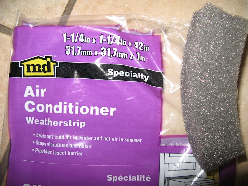
I decided to fill the gap with some soft foam that I purchased at Lowe's:
I cut out a rectangle that is bigger than the switch and about 3/4" thick. I then cut out the middle just enough so the LEDs wouldn't be blocked (upper left). Next, put the rocker back on and make sure it still clicks up and down correctly (upper center). Next, I connected it to power to make sure the LEDs still looked good. Finally I trimmed off the excess foam and marked up the outside of the foam with a Sharpie (right and bottom):
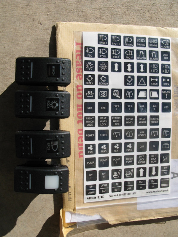
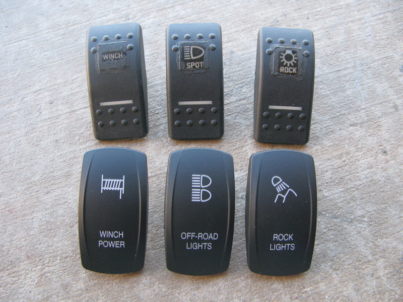
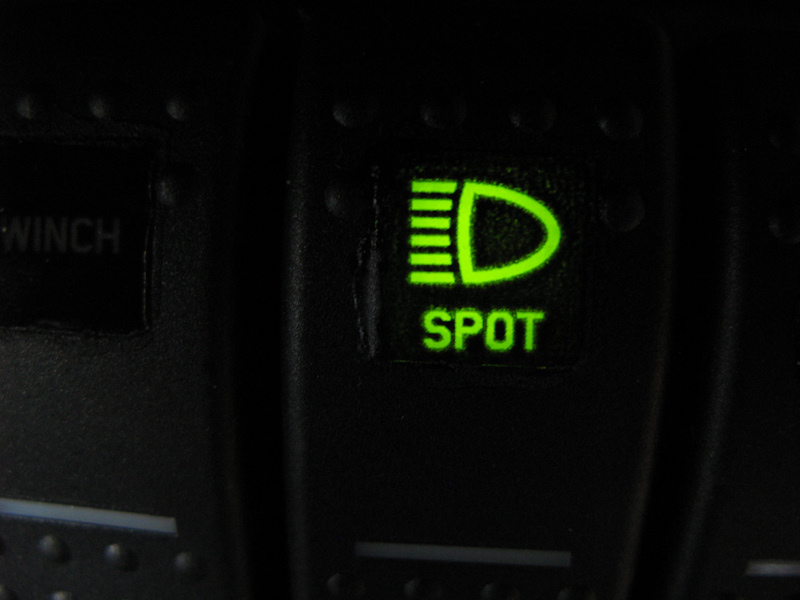
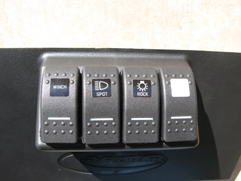
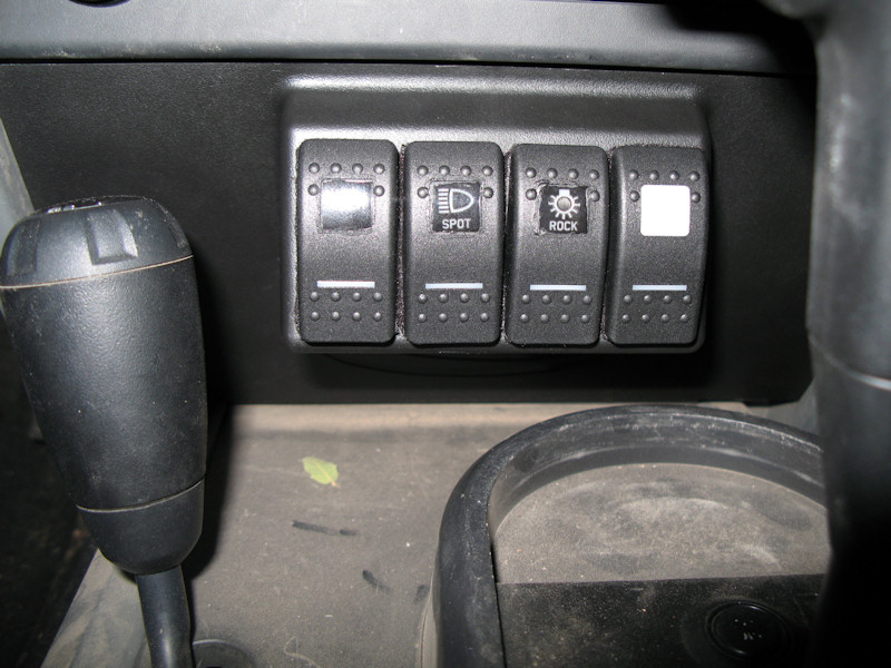
Switch Installation:First, I wanted to label the switches. All of the stock switches in the Jeep have white lettering on black, and the lettering is illuminated green when the lights are on. The only place I could find labels was in the UK. The owner was friendly and helpful explaining the white (clear) lettering on the black has two problems - they are hard to see during the day, and at night they have light bleed around the edges. I figured I would give them a shot and if they don't work out get the black letting on the clear background. Here's the sheet of legends with three of the switches labeled:
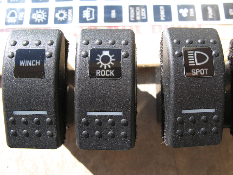
A close up of the switches look good, but I don't think they look that good fro the drivers perspective:
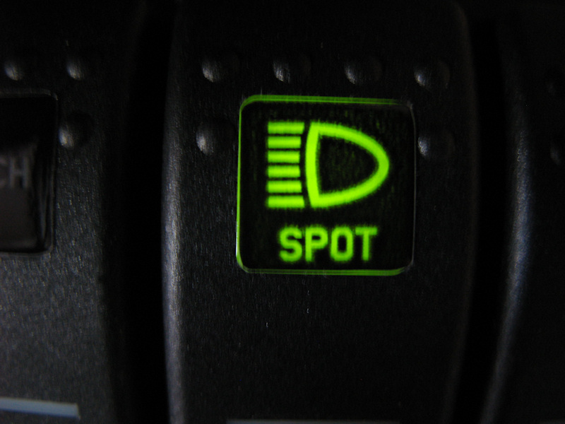
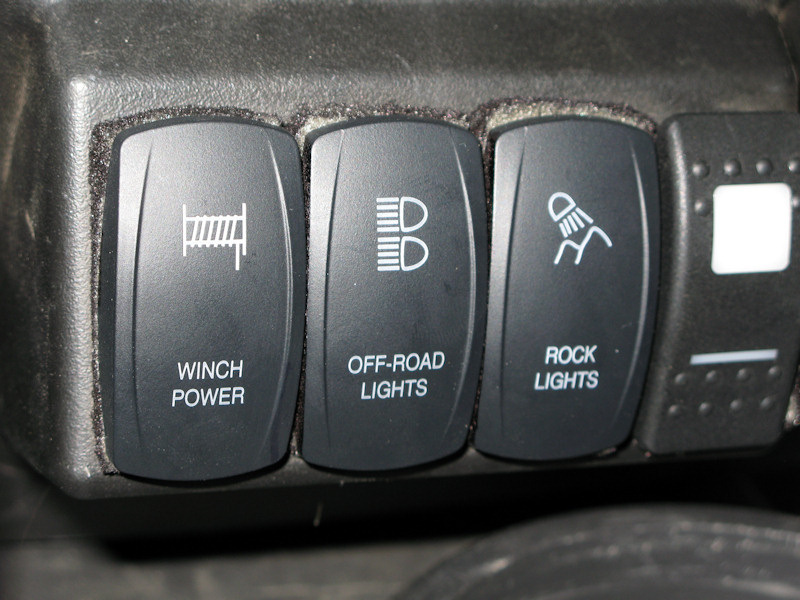
Update - OTRATTW just came out with laser etched rockers - looks a lot more professional:
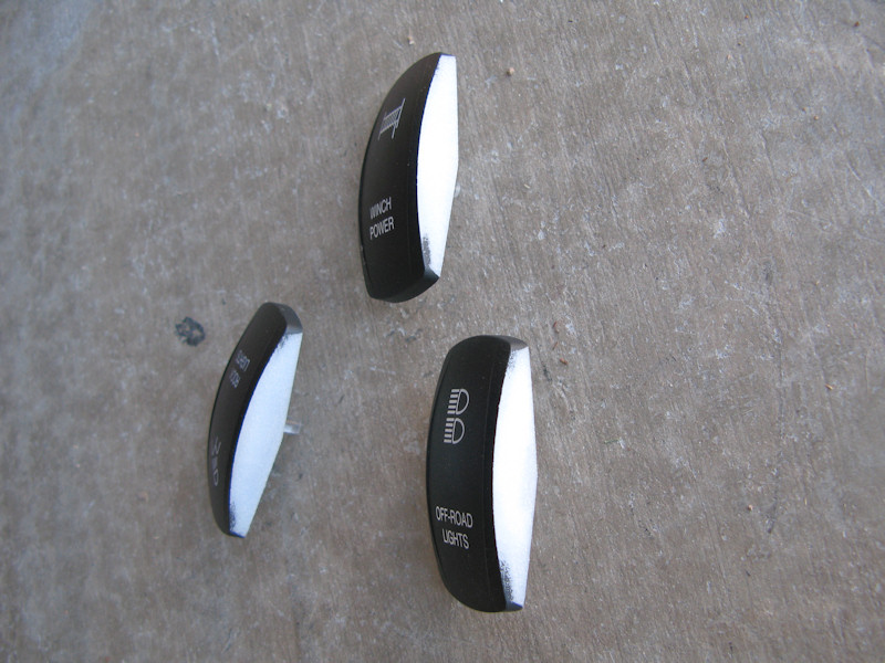
Since it's an aftermarket part for the Jeep you know it would have to be modified. The new switches are a little too wide and need to be sanded a bit. After sanding mark the white plastic with a black Sharpie:
Also, as expected they do bleed around the edges:
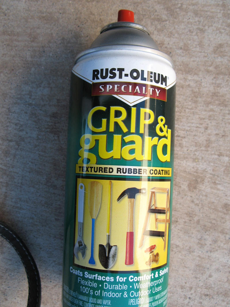
I had some of this stuff in the garage and decided to see hoe it worked on filling in the edges:
I sprayed some of the Grip and Guard into a paper cup and using a toothpick dabbed it around the edges of the stickers. Looks good for now:
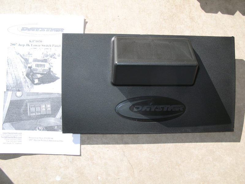
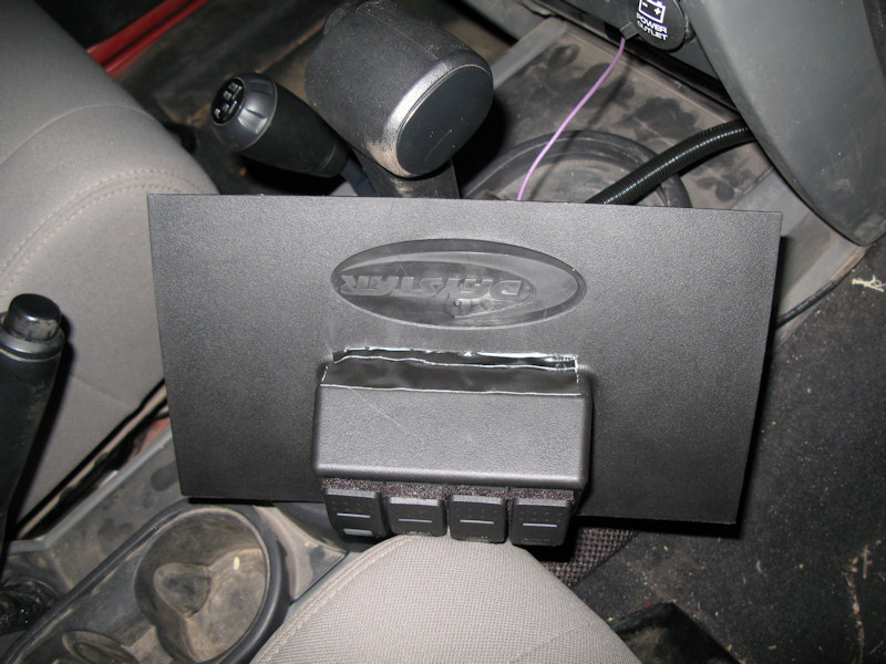
I found there wasn't enough room behind the lower panel for the switches, so I purchased a Daystar Switch Panel:
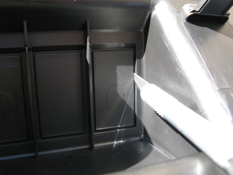
Carefully cut out the four holes for the switches - don't cut too much:
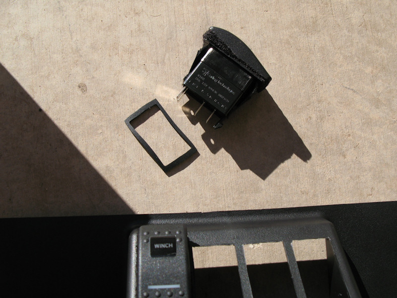
Trim as necessary and install each switch with a gasket:
All installed:
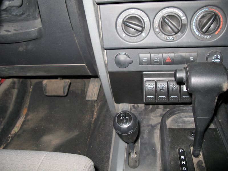
The new switch covers all installed:
Carefully remove the lower panel:
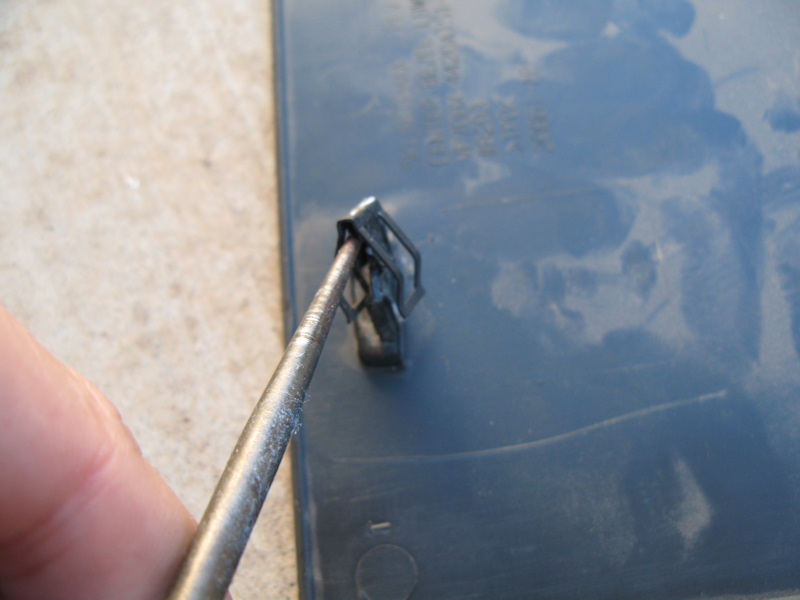
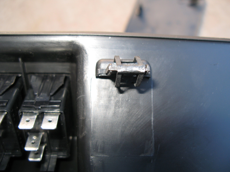
Remove the two clips from the back of the lower panel:
And install them on the Daystar Panel
Test fit:
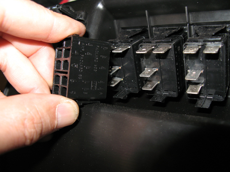
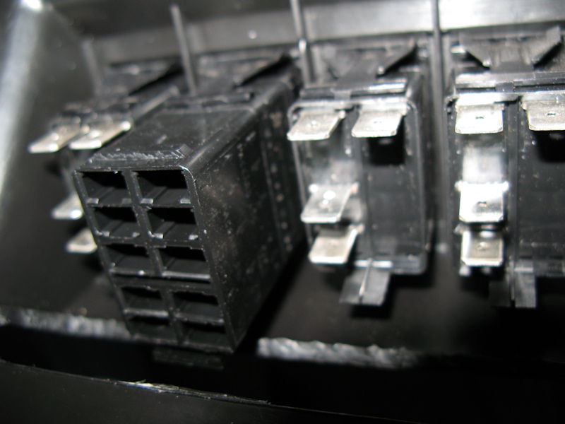
Test fit of the connector from the rear - doesn't fit:
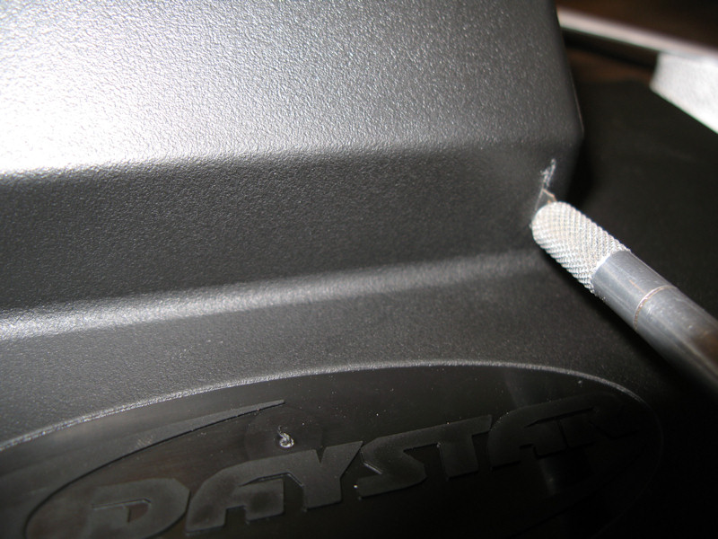
Have to cut this bump out of the bottom of the panel - it won't be visible when installed:
With the cutout the connector fits:
Put the connector on all four switches and clipped the panel in place to ensure no interference in the rear:
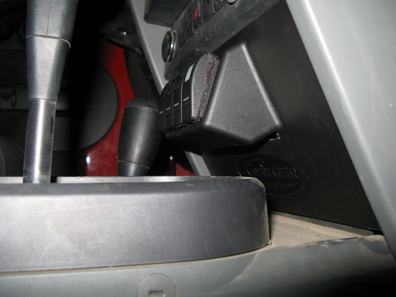
A view from low on the side - you can't see the cutout:
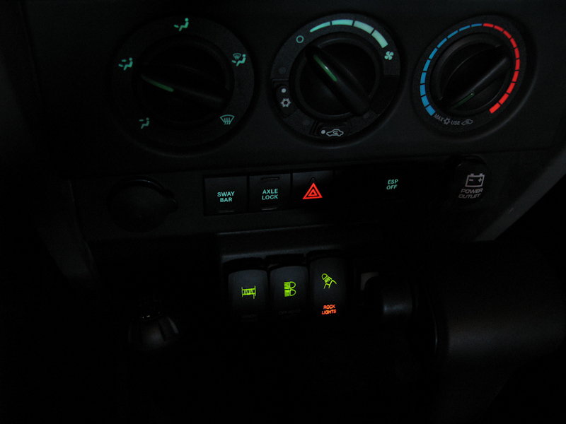
A view of the switches with the Rock Lights on:
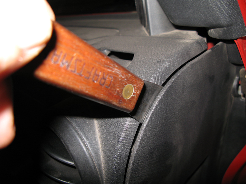
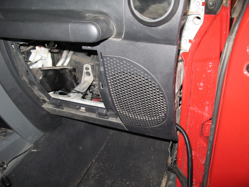
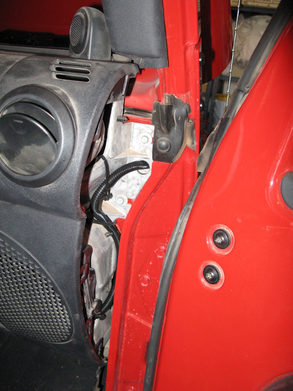
Installation of the switch wiring harness through the firewall:Carefully remove the passenger side panel:
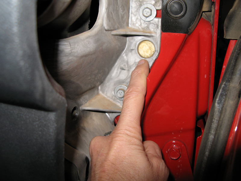
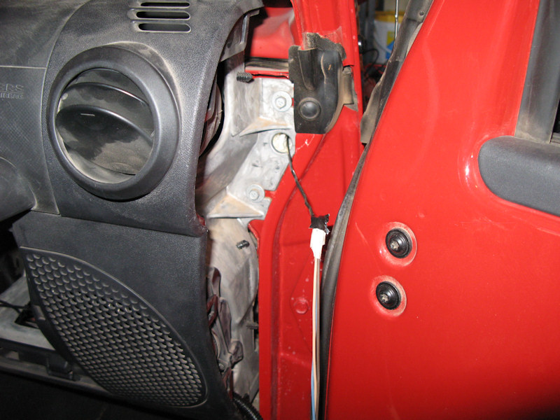
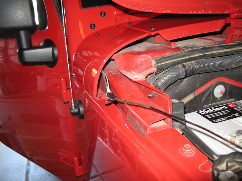
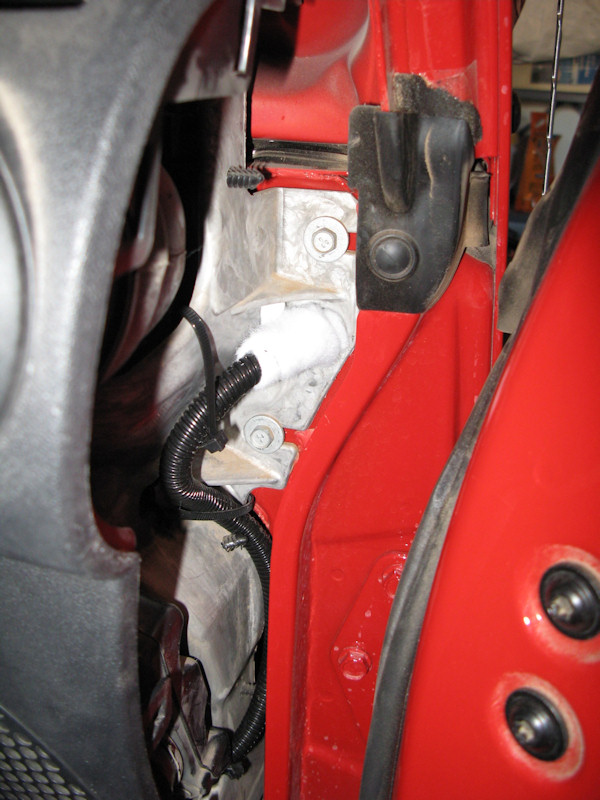
We're going to run the harness through this foam filled hole in the firewall:
I pushed a rope through the foam with a screwdriver to help clear out the hole and make room for the harness:
Take the finished switch panel and run the purple wire into the loom:
Not necessary, but I taped up the hole under the switches:
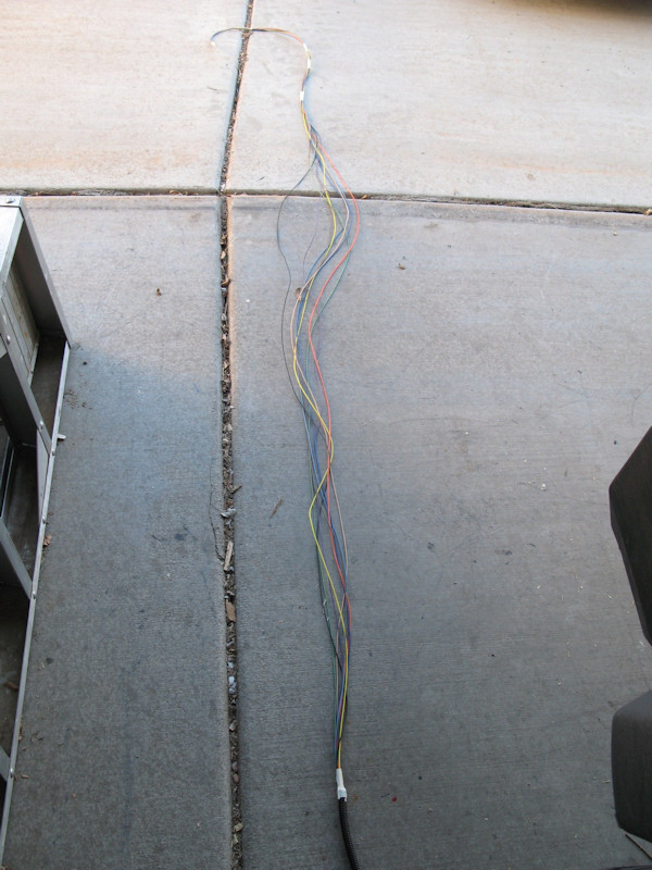
Straighten the wire and tape in spots:
Running the wire bundle:
Install the panel:
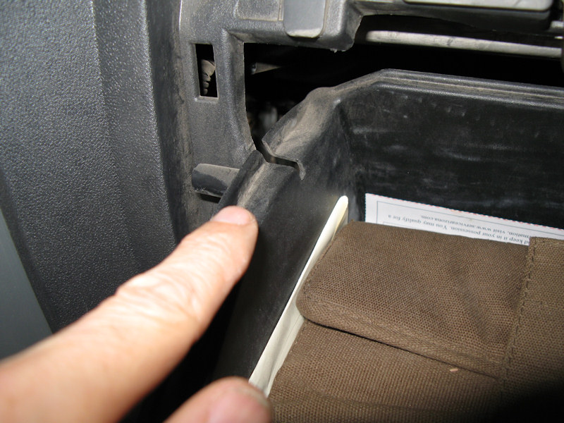
Remove the glove box (push in the side to get past the stop):
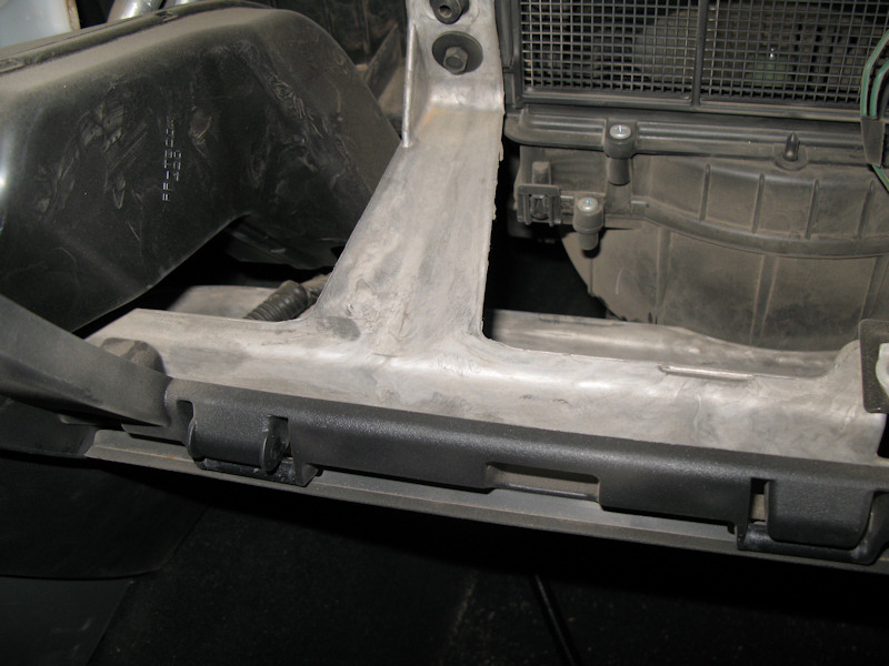
Run the cable up just under the metal:
Run the bundle out the side and strap it in place:
Push a wire thought the hole and tape the wire bundle to it:
Pull the bundle though:
Secure the bundle on the inside:
Add some insulation into the hole:
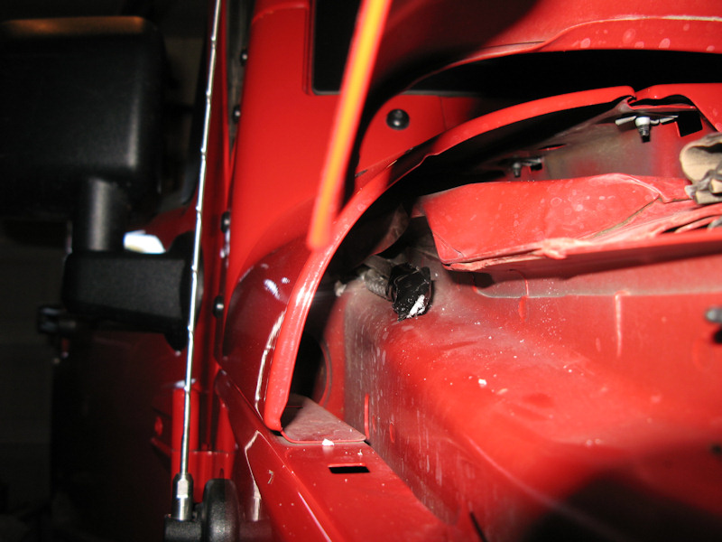
Run and secure the bundle under the hood:
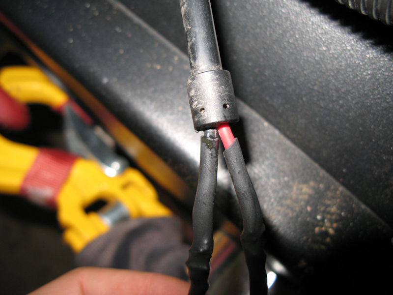
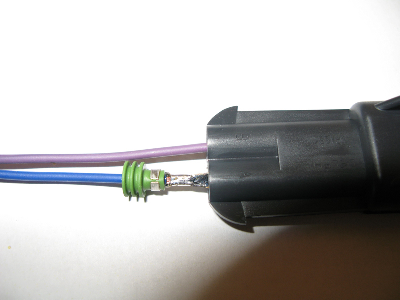
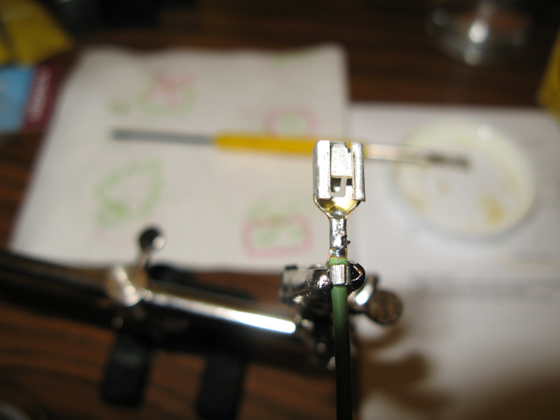
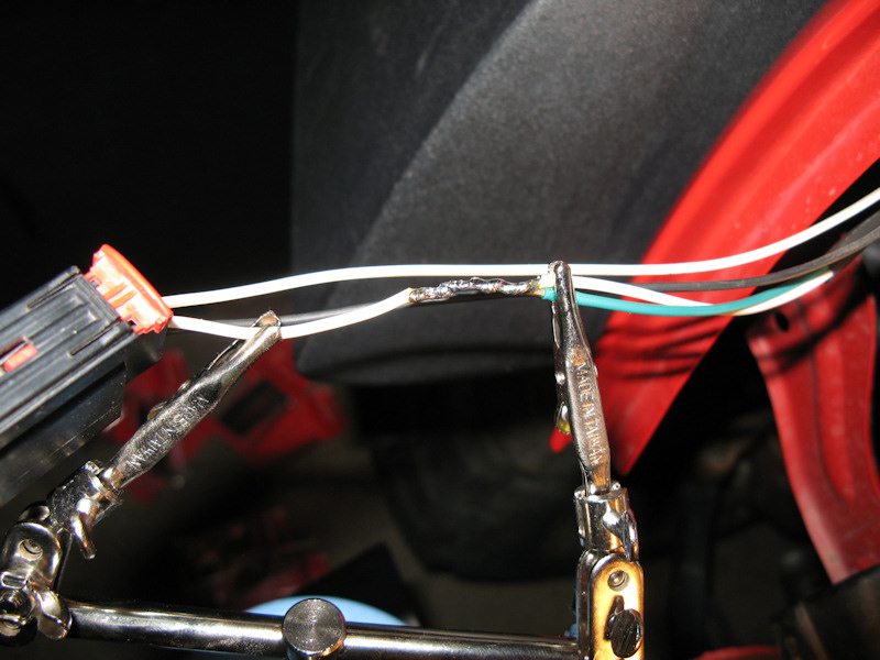
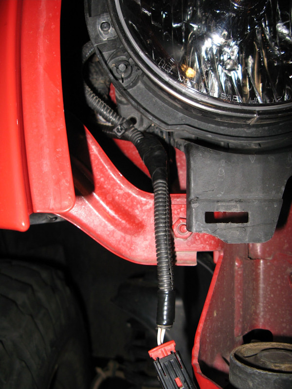
Wiring the HIDs:The HIDs combined draw 6.6 amps and I used 12 Gauge TXL wire for all connections. Each connection was soldered, protected with heat shrink tubing wrapped in tape and set in a split loom for protection. This connection was soldered and had the heat shrink tubing installed:
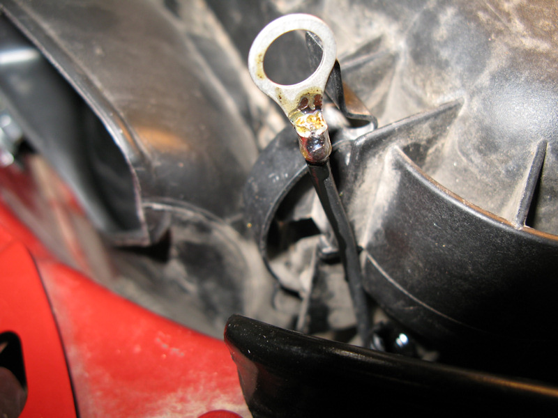
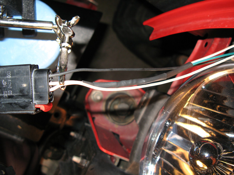
I ran the wires through split looms, found a good place for the ground, and cut the wire and soldered on a terminal:
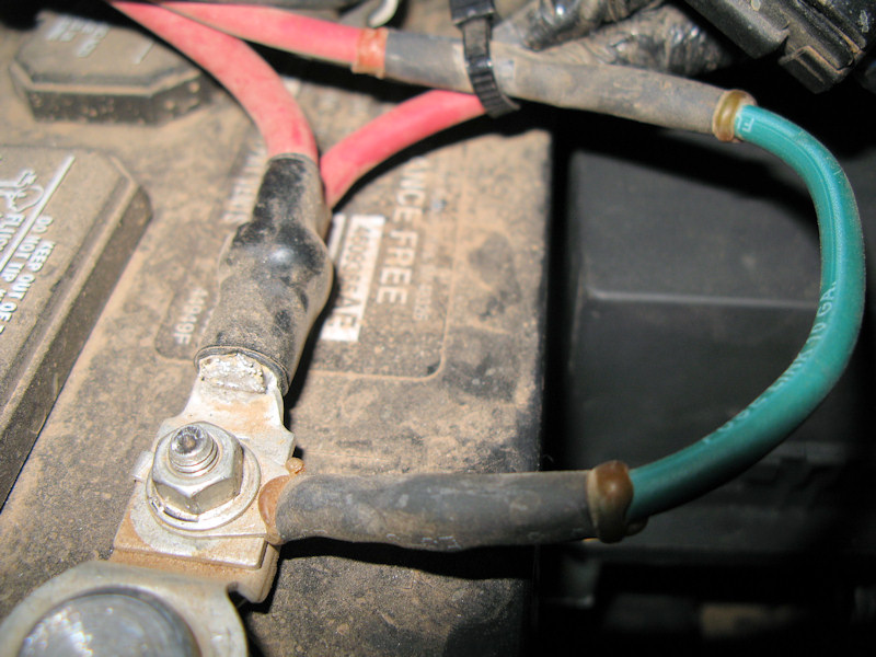
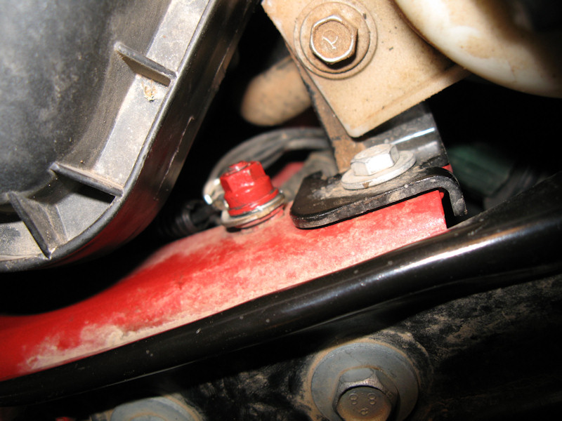
Connected the ground to the existing ground lug:
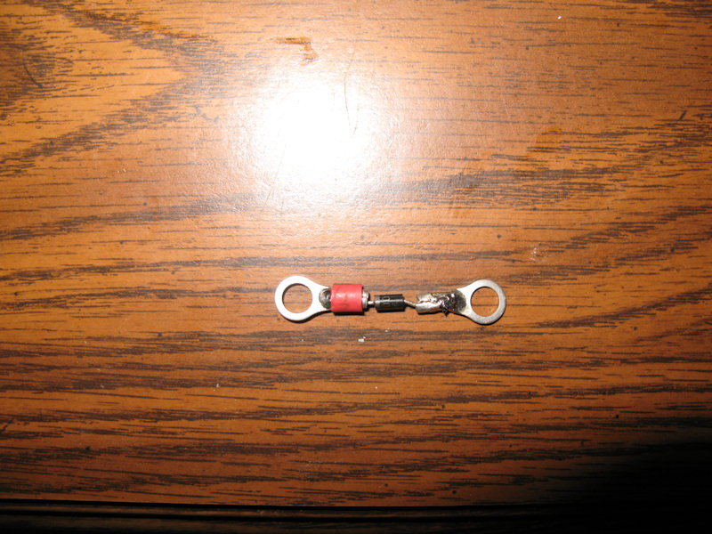
Wiring the Winch:I tested the winch relay and found that when the relay is opened (de-energized) a large spike is sent back down the positive wire and it causes a spark similar to a spark plug. A little research showed this is normal, and can be fixed with a diode. I wired one up - note the red marker installing the diode backwards would cause a short:
Protect it with heat shrink tubing:
Installed on top of the relay - the red side will be to the battery, and the other side is connected to ground which I already wired:
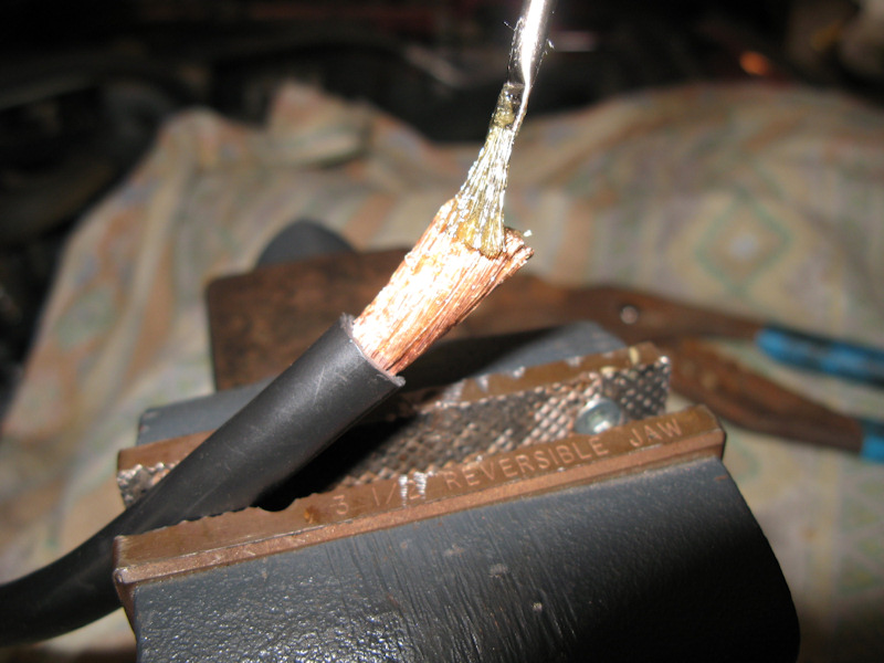
The wiring for the winch is 2 gauge. The ends are all prepared in a similar fashion. First cut the wire to length. I don't have good wire cutters for wire this thick so I used a hack saw:
There are two types of terminal lugs. Ones that are closed at one end, and ones that are open at both ends. I decided to get the ones that open at both ends so I could crimp and solder easily:
If you have heat shrink tubing that just barely fits on the wire, now is the time to slip it on. Also, before crimping coat the wire with rosin based flux:
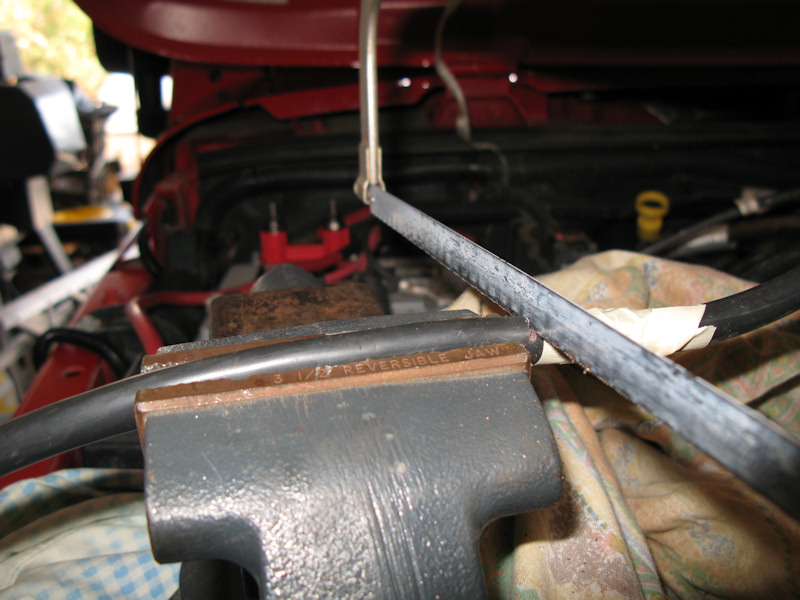
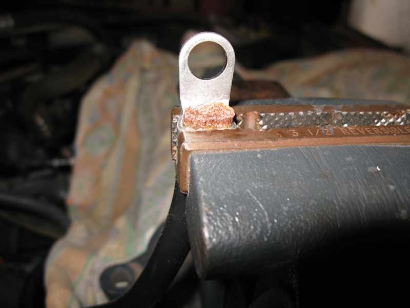
I used a vise to crimp the lug. You can use a piece of masking tape to temporarily hold the lug in position while you are crimping:
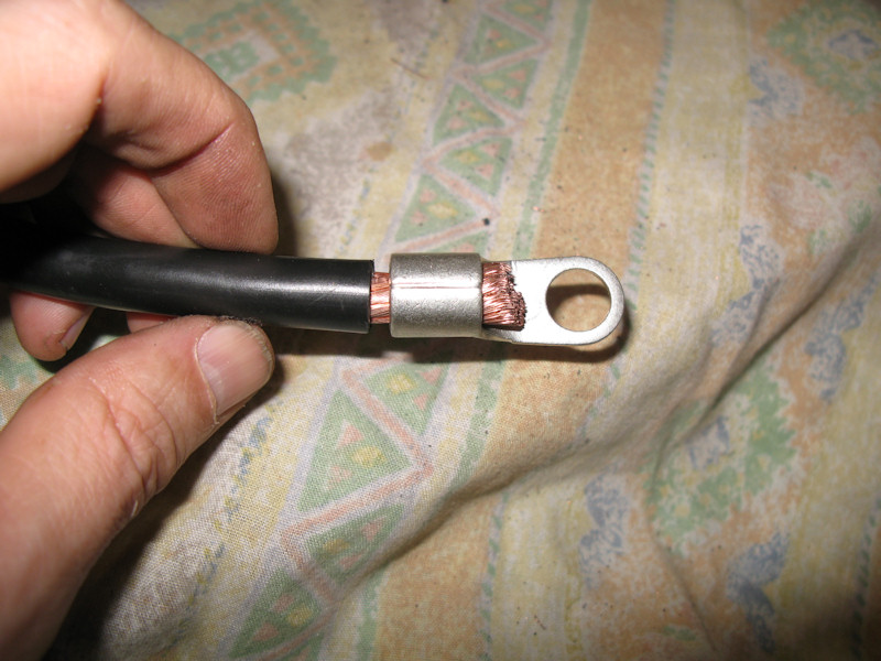
You'll need some type of torch to heat the wire. I held the wire in place (loosely) with some vise grips. Heat the lug just above the wire and the tip of the wire. When it's hot enough the solder will get sucked into the wire. I also soldered the tip of the lug and the back:
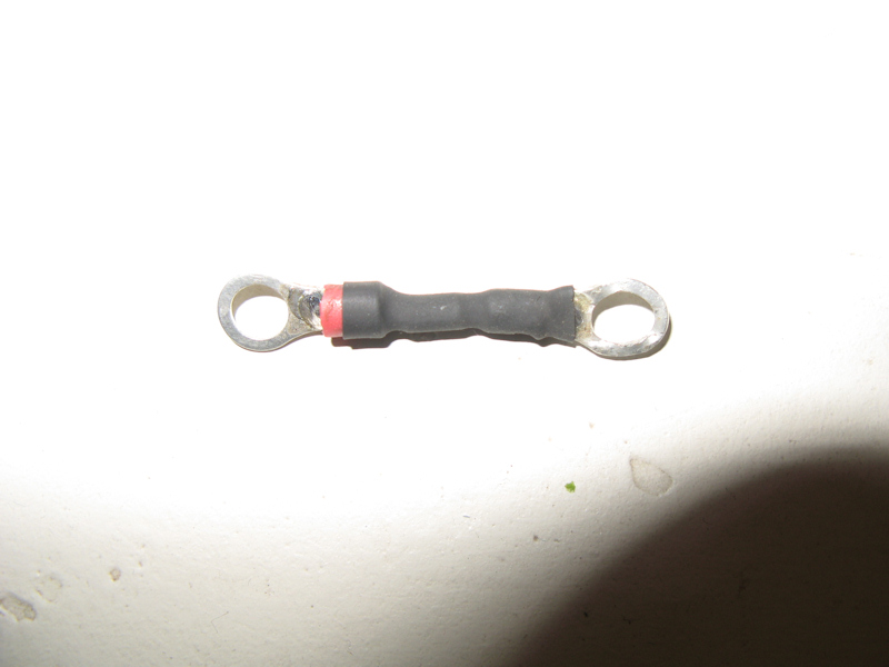
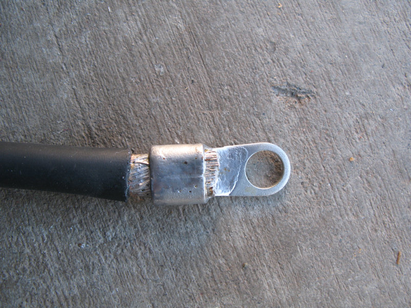
Position the heat shrink tubing (I used two layers), protect it with a wire loom, and bolt in place:
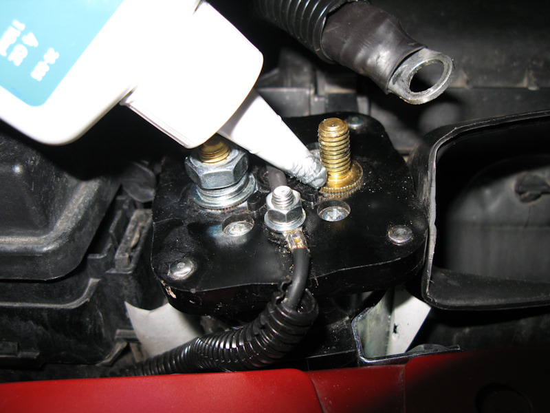
If you are connecting two dissimilar metals it's not a bad idea to use some Anti-Oxidant:
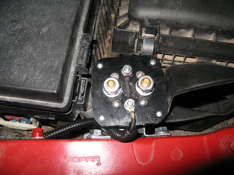
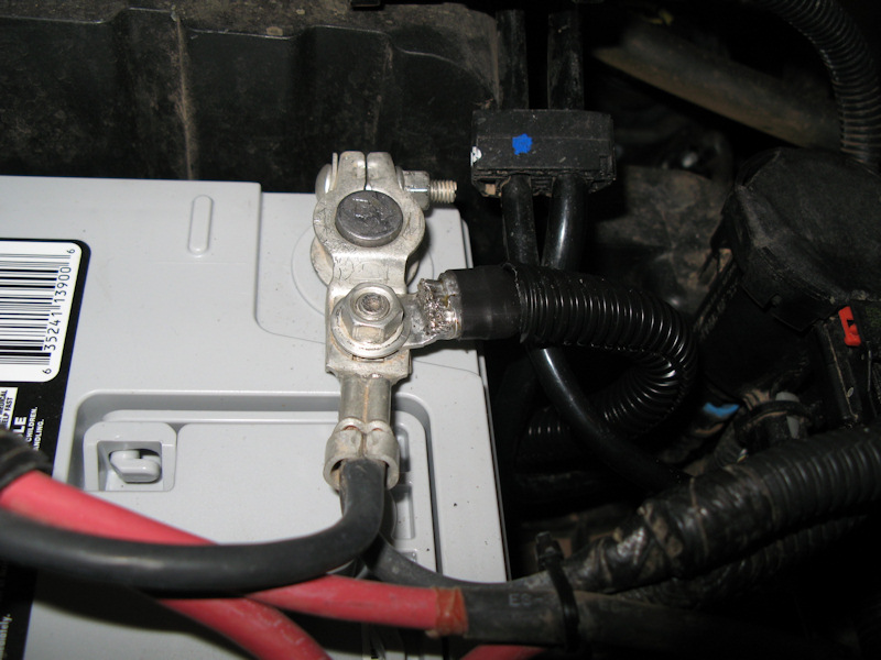
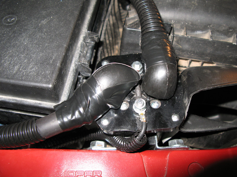
The power wires on the winch relay. To protect against accidental shorting, I cut some PCV valve rubber elbows and put them on the terminals:
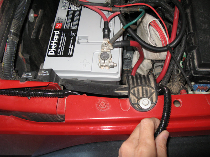
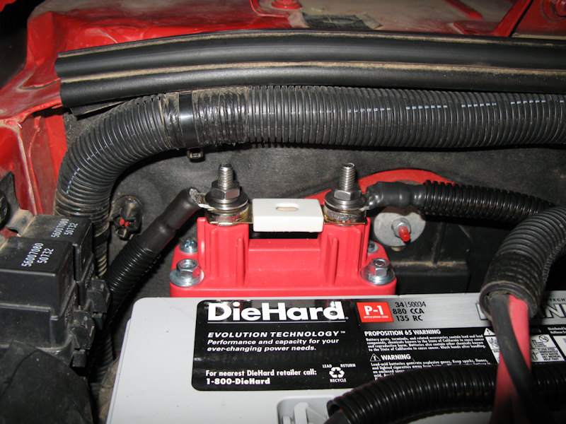
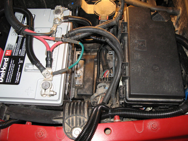
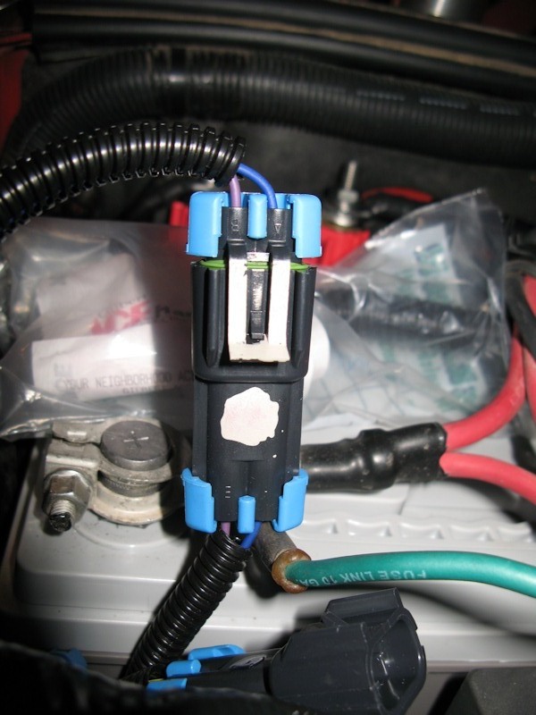
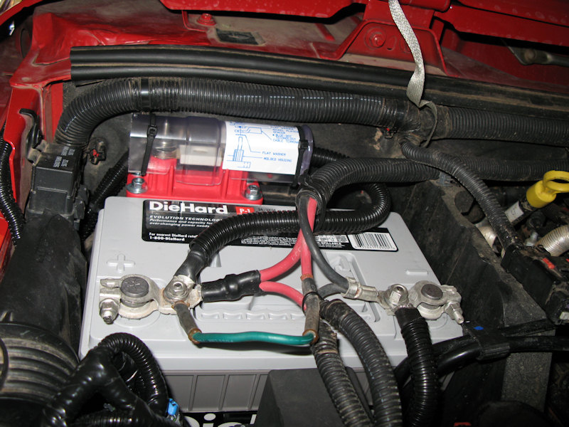
Since the winch won't be directly wired to the battery (there's a relay in the middle) I decided to use an ANL fuse to protect the circuit. The winch should max out at 416 amps and the relay at 500 amps. Looking at the reference ANL Data Sheet, it appears a 250 amp fuse should work the best. I purchased a ANL fuse holder that can handle more than 500 amps. I found that it fits just behind the battery, and can be secured with the two longer legs resting on the battery tray and the two shorter legs tie wrapped to the Jeep:
Secured in place behind the battery:
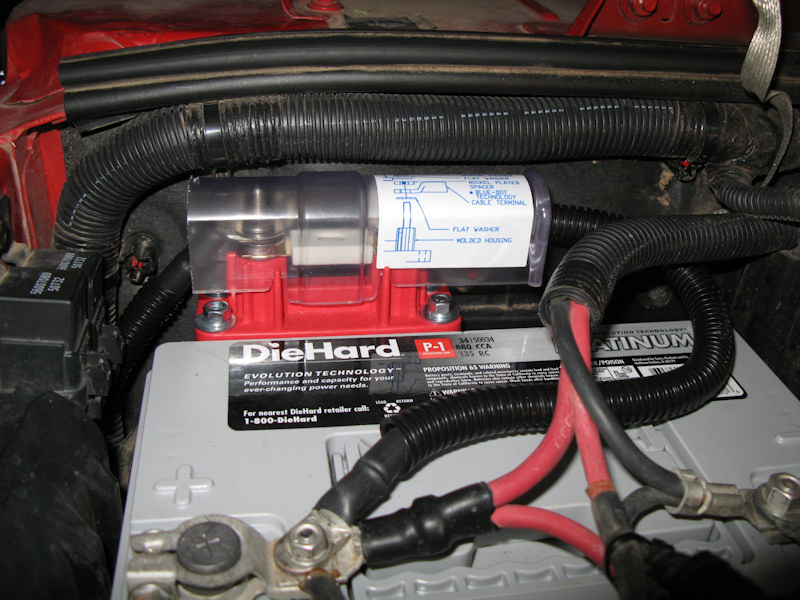
Wired up with the fuse in place:
It comes with a protective cover. I'll tie it down when I'm finished wiring the fuse box:
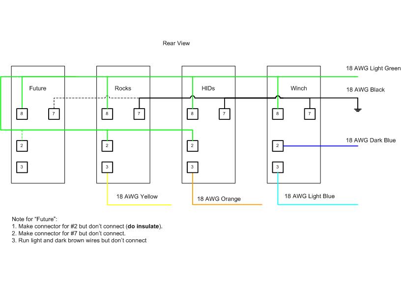
Wiring the RTMR Panel:I wanted to wire the RTMR Panel so it could be removed and re-installed fairly easily as I haven't decided all of the circuits I will house in it, so I have all wires in connectors. Here's the wiring diagram:
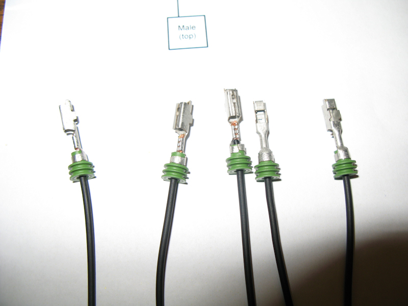
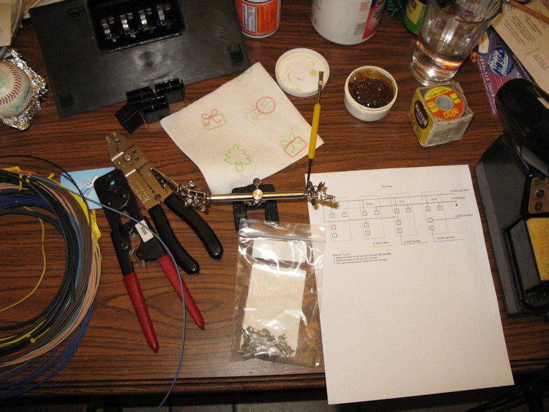
Gathering the components. All terminals are Metri-Pak 280:
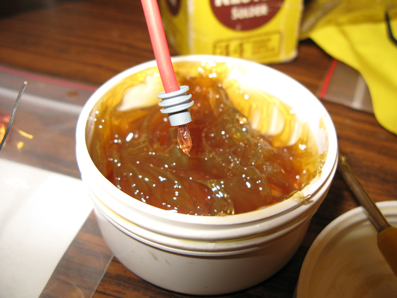
Cur 1/4" off the tip of a wire, insert a seal, and dip the end into rosin based flux. The terminals will be crimped, but I want to solder them too:
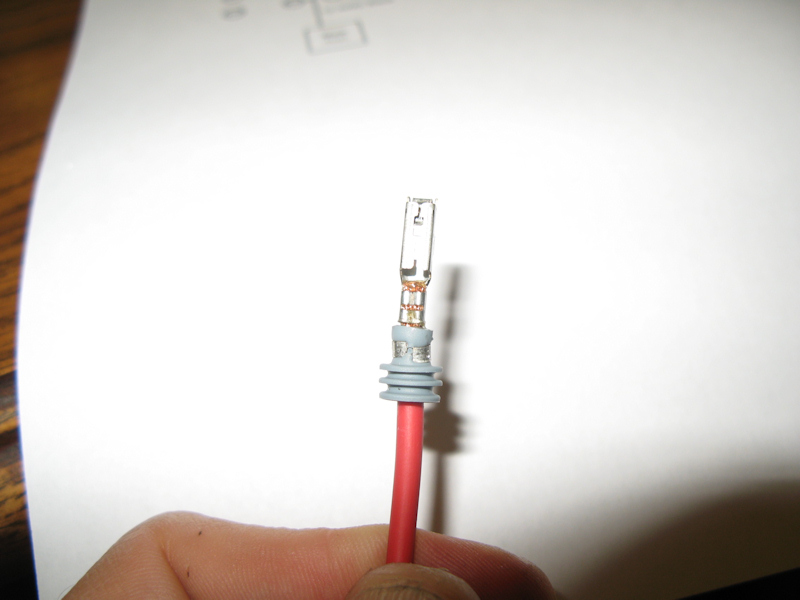
This terminal is for the bottom of the panel and is ready to be crimped:
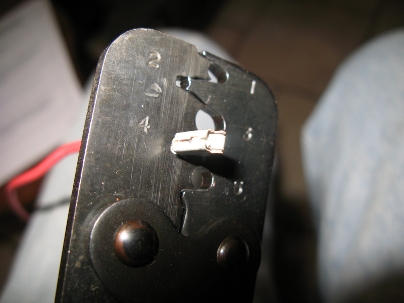
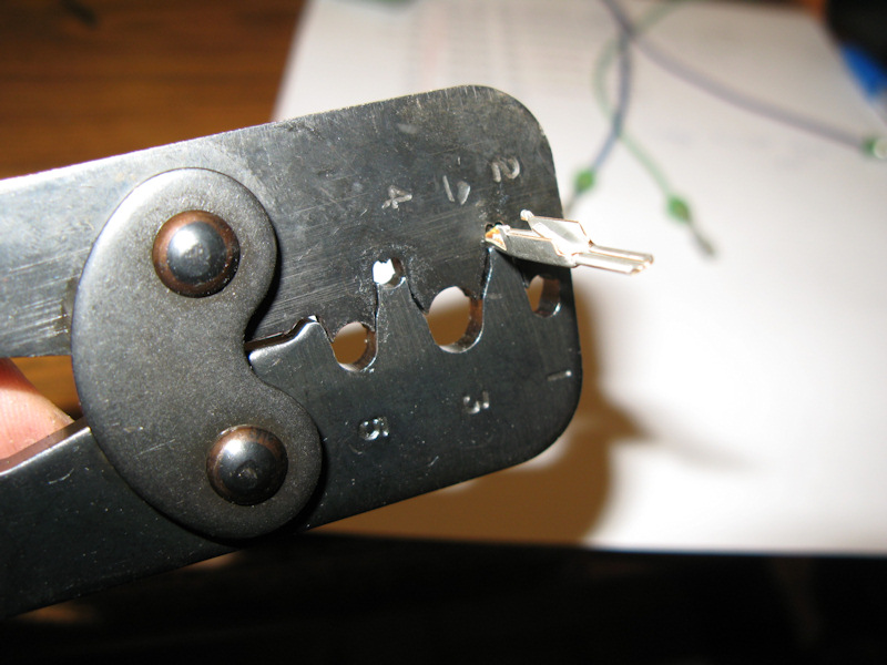
Crimping the terminal. Hole 4 is for 12 AWG wires, 2 is for 18 AWG wires, and 5 is for the seals. Do yourself a favor and purchase one of the specialized crimping tools for your terminals:
Crimped terminal wiring:
Crimped the seal:
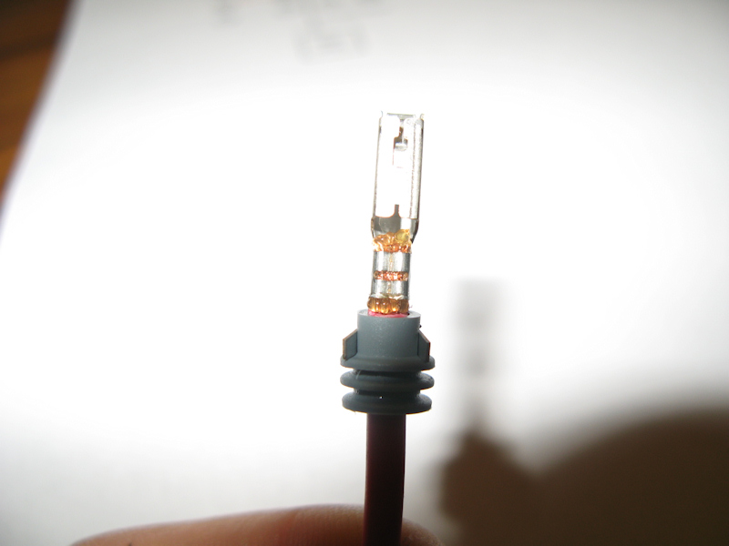
Soldered and ready for installation:
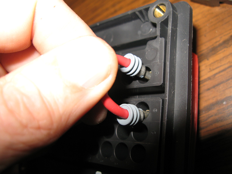
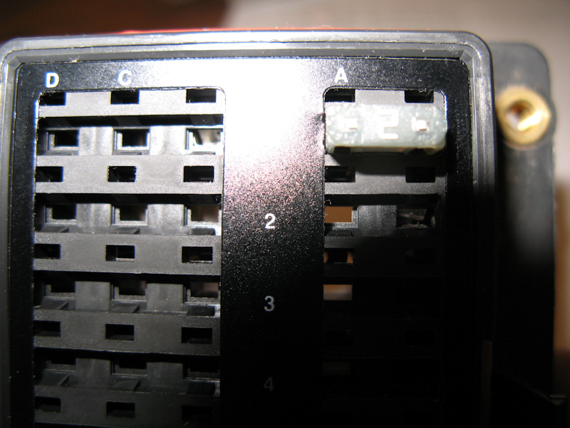
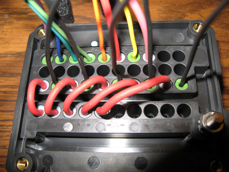
Inserting the power wire for one of the relays:
Inserted in place - you should hear a click when it's in place:
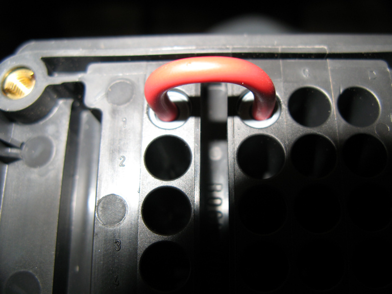
Also, from the top you should see the terminal set flush and in this case the fuse should sit in place
All of the relay power wires in place:
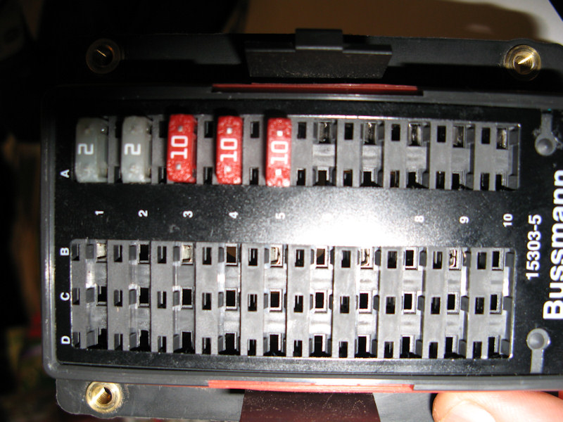
Fuses in place:
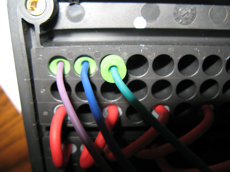
Wiring the other wires according to the diagram:
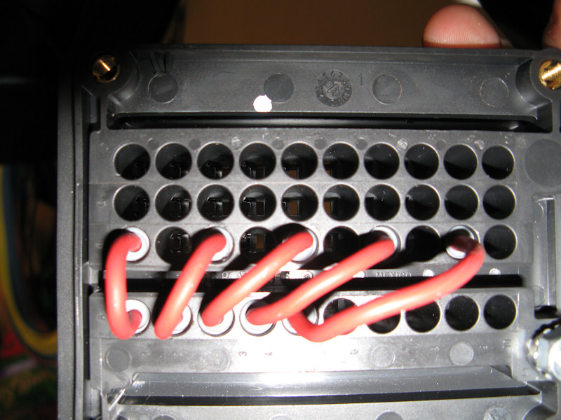
The ground wires:
Inserted:
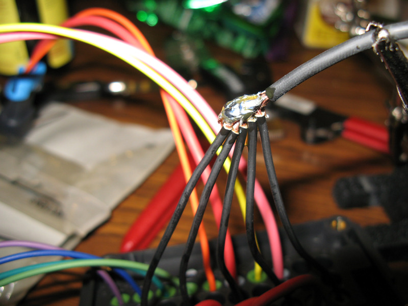
Combining all ground wires and starting to solder. Not pictured I ended up using a pencil torch to get enough heat for the solder the connection properly:
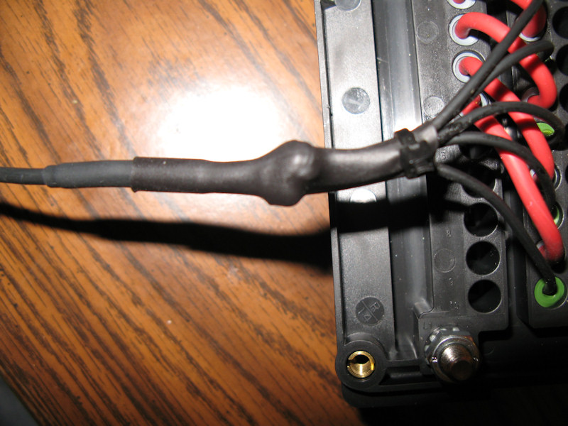
Use some heat shrink tubing:
Add plugs for the unused (for now) holes:
All sealed - this end is done for now:
Insert all five relays:
Crimping a terminal for the connectors for the other end of the wires:
Inserting the terminals into the connector:
Use a plug for the unused wire. You may ask why I didn't just purchase a 1 terminal connector. The cost of a 1 terminal connector is excessive because there is a minimum purchase for the connector components:
Add these blue clips to the end to the end of the connector as a strain relief:
Adding wire looms:
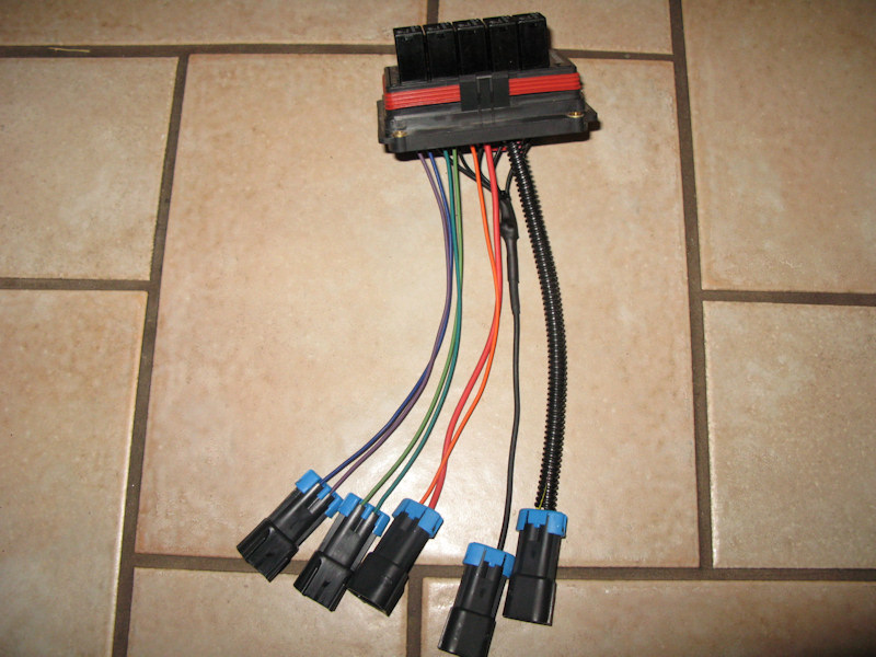
Looms on all wires and color coding at the connector ends. Ready for installation:
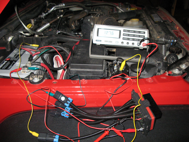
Not so fast. Even though you know you wired everything properly don't you think you should test your work? Yes you should. I hooked the positive bus and negative wire to the battery. Then, one by one I hooked power to each relay and measured the output. Everything checked out, so now it's ready to be installed:
Wiring the Switches:Here is the wiring diagram for an individual switch (Circuit 1, Lamp G/7). The switches have a dashboard light circuit for an LED (power on pin 8 and ground on pin 7), and a switch circuit (power on pin 2 and output on pin 3). There is also a "switch on" LED that uses the power from pin 2 and ground on pin 7. The use for the "Future" switch is not know at this time, so pin 7 will not be connected (so it won't light with the dashboard), a wire for pin 2 will be made but not connected (in case the switch is used for a light), and light brown and dark brown wires will be run but not connected to permit a connection like the "Winch", or either of the lights:
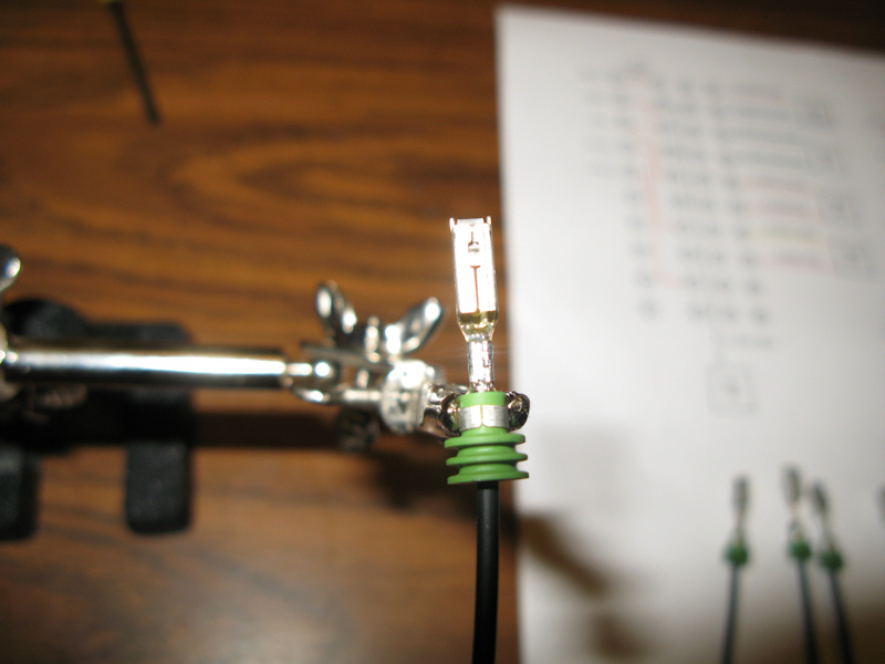
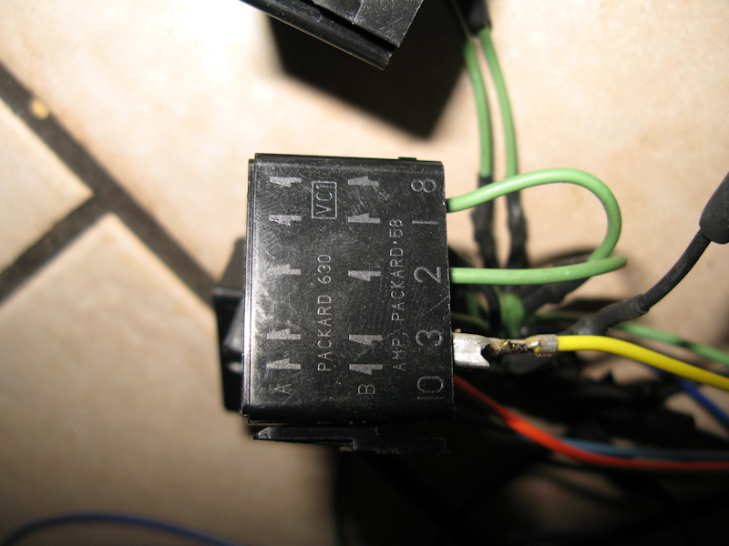
Ready to start. I'm using Delphi / Packard - 630 terminals:
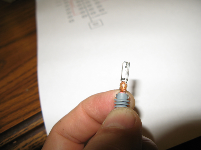
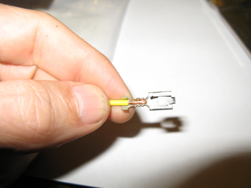
The terminals are similar to the terminals in the RTMR Panel. First, stop 1/4" insulation, dip in rosin, and position the wire:
The tabs for there terminals stick out a little too much for the Metri-Pack 280 crimping tool, so they need to be squeezed in a little first:
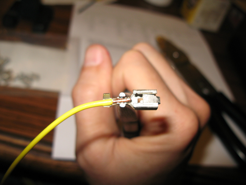
Crimped. Next, when the tab for the insulation is crimped it needs to set better with some needle nose pliers. A crimping too for Delphi / Packard - 630 terminals would have done a better job, but the most important crimp - the one for the wire turns out fine:
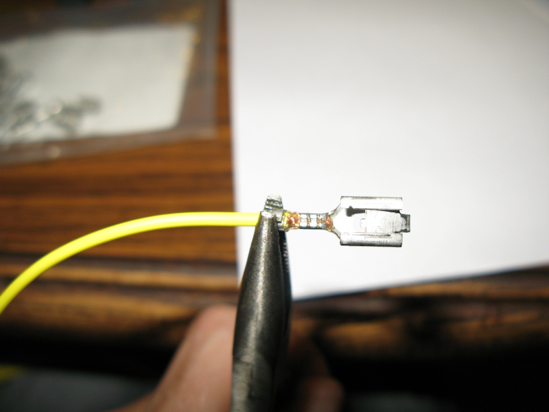
Soldered:
Once all terminals are soldered, they can be inserted into the switch connectors. The pin identification (bottom) and direction for the tang (top for Packard 630) are marked on the connector. They should click into place:
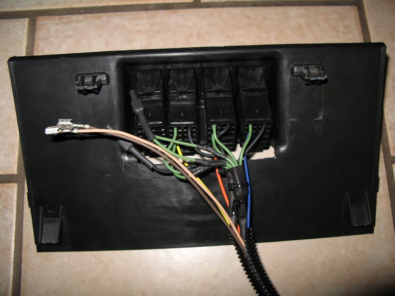
The ground wires connected (the last connector is not connected yet because it is currently unused):
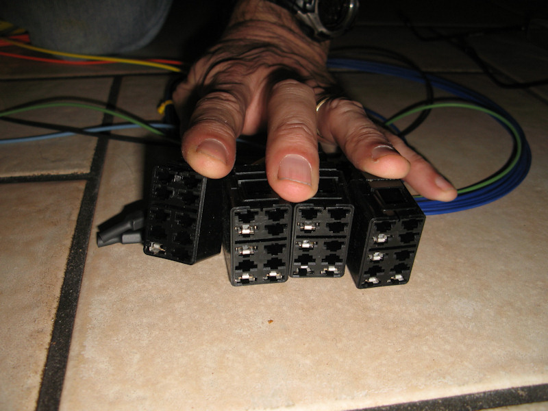
All wires connected. Look at the front to ensure they are all seated properly:
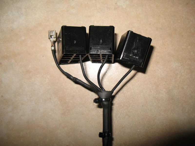
Connect the terminals to the switches. The power and ground wires have some heat shrink tubing for now that can be removed when the spare switch is used. Also the brown wires are ready to be used for the spare switch. The wires are all run in a wire loom for installation:
Test the switch wiring. Connect the light green wire to power and the black wire to ground and the switch labels illuminate. Also test each "on" light and switching power. All ready to be installed:
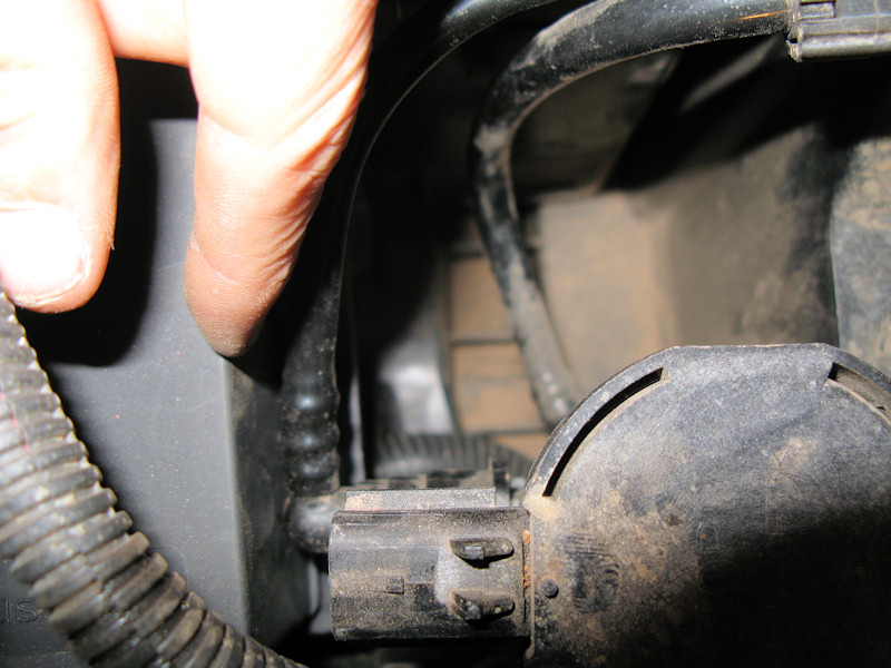
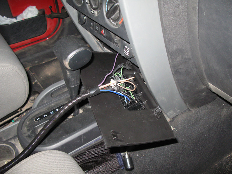
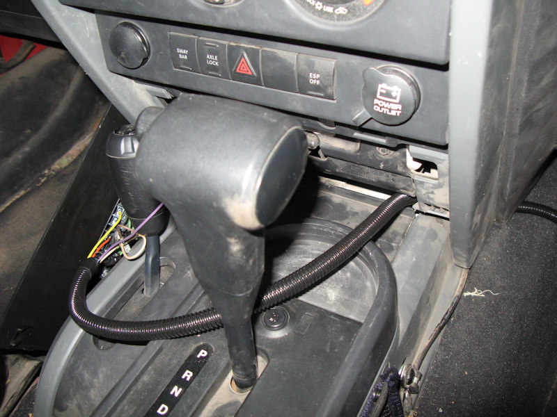
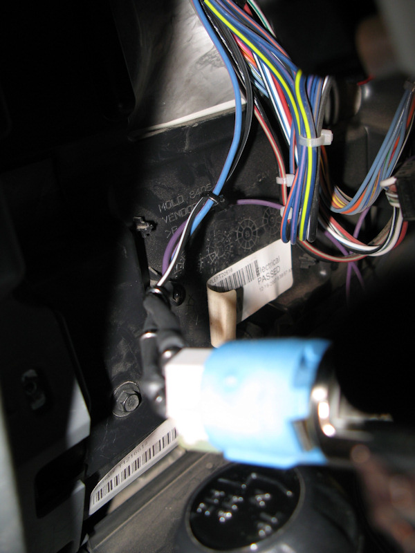
Power/Lights On Wiring:Need to find a wire to be used as a "ignition on" switch. The cigar lighter is turned on with the ignition, it's fused, and is designed to handle a load, so it makes a good place to identify when power is on. I connected one end of the purple wire to the power side of the cigar lighter (the other side will be connected to the "ignition on" relay):
Need to find a wire to be used as a "lights on" switch. I checked the wiring diagram, and the circuit for the parking lights and side markers are designed to also be used for the trailer towing package. I used the passenger side parking/turn light. The middle wire is for the parking light. Soldered the green wire to the connection:
Two layers of heat shrink tubing:
In a loom and tied back in place:
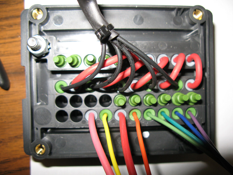
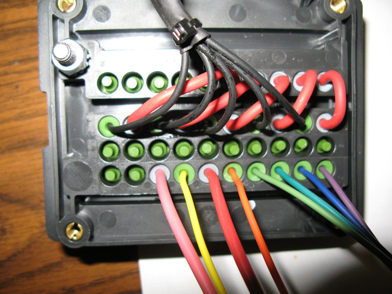
Wiring to the RTMR Panel:The winch wire has been run, all wires that need to be connect to the RTMR Panel have been run, and in the looms are hanging down at the bottom of the picture:
Build up the power wire for the RTMR Panel:
Connect the power wire to the fuse block and the bottom of the RTMR Panel. I put a rubber cap on the screw/bolt:
Flip the RTMR Panel back and set it in place:
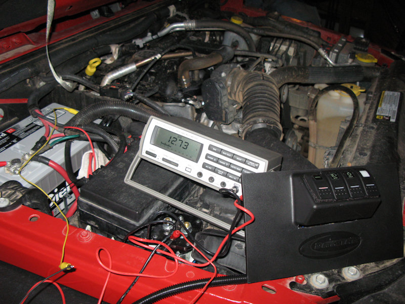
Before final assembly test the circuits with jumper wires:
Secure the RTMR Panel and ensure it doesn't rub against anything:
Start making the connections. The black wires are connected together and to a ground:
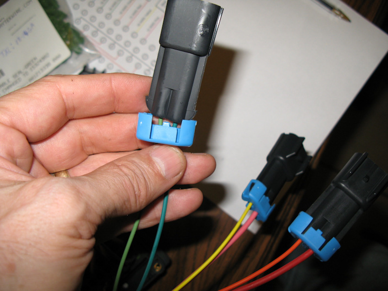
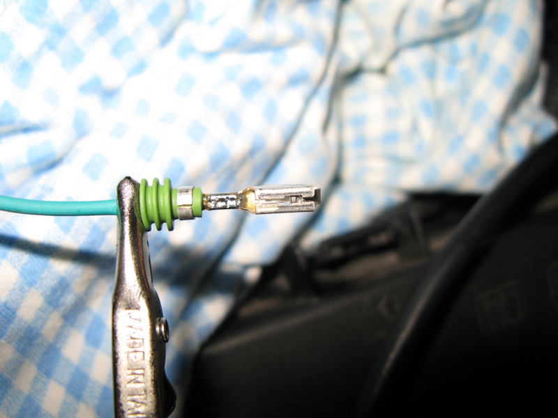
Terminals have to be made for he plugs. These plug into the plugs on the RTMR Panel:
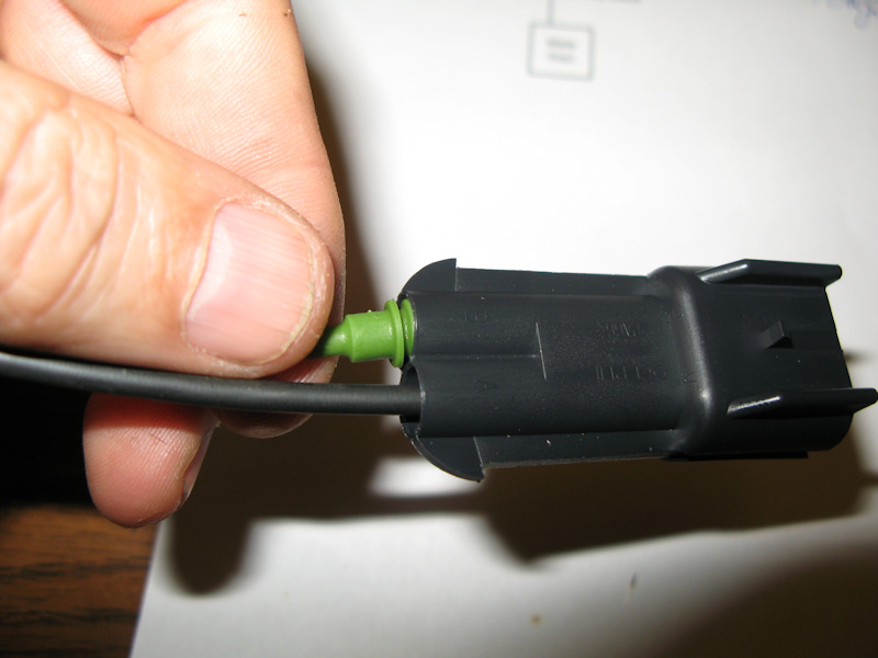
A completed connection. In addition to the wires matching on both sides of the connector I color coded the plastic connector ends:
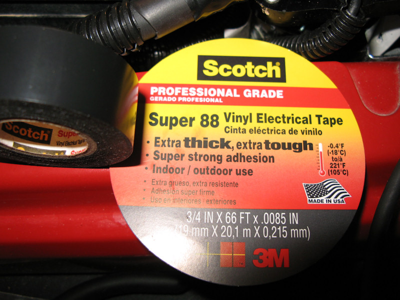
When all of the connectors are in place you need to tape the bundles together - including the ends of the looms. Do yourself a favor and get some good electrical tape:
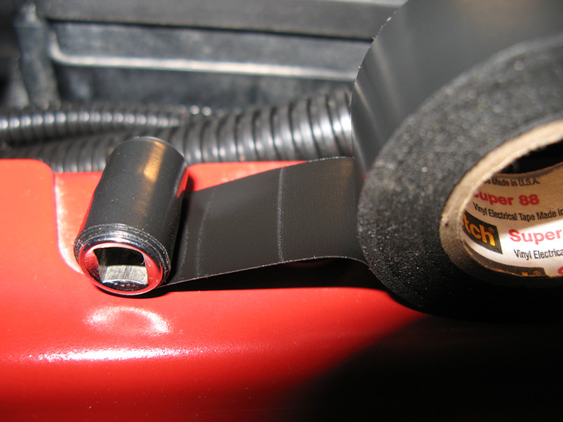
Sometimes it's hard to get around tight corners with a big roll of tape, so you can roll some tape on a small socket and use that for taping:
All taped and tied into place:
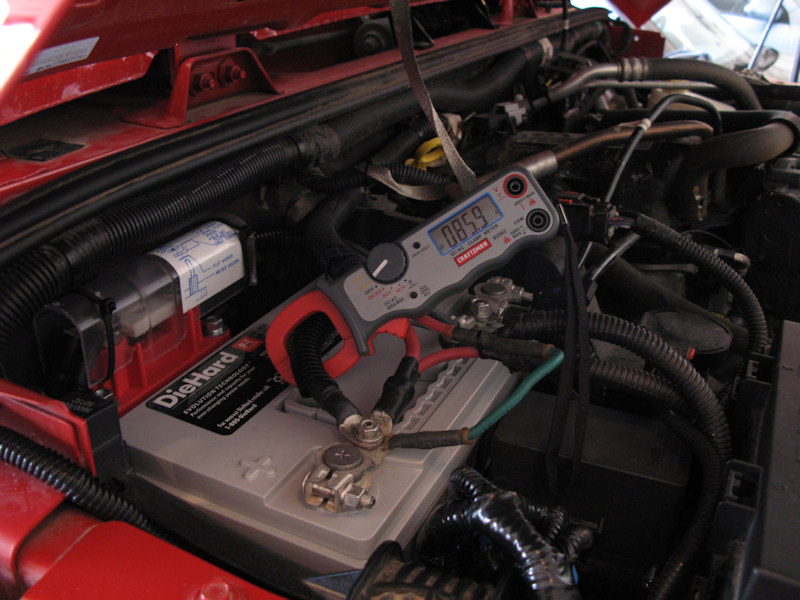
Testing with the HIDs and winch (no tension) turned on. I noticed that the winch can spike to 200 amps when first turned on:
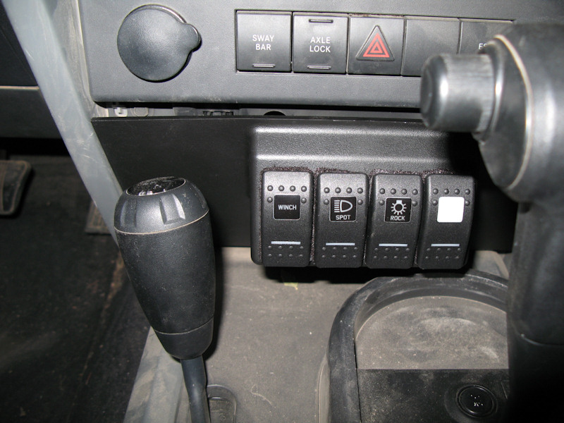
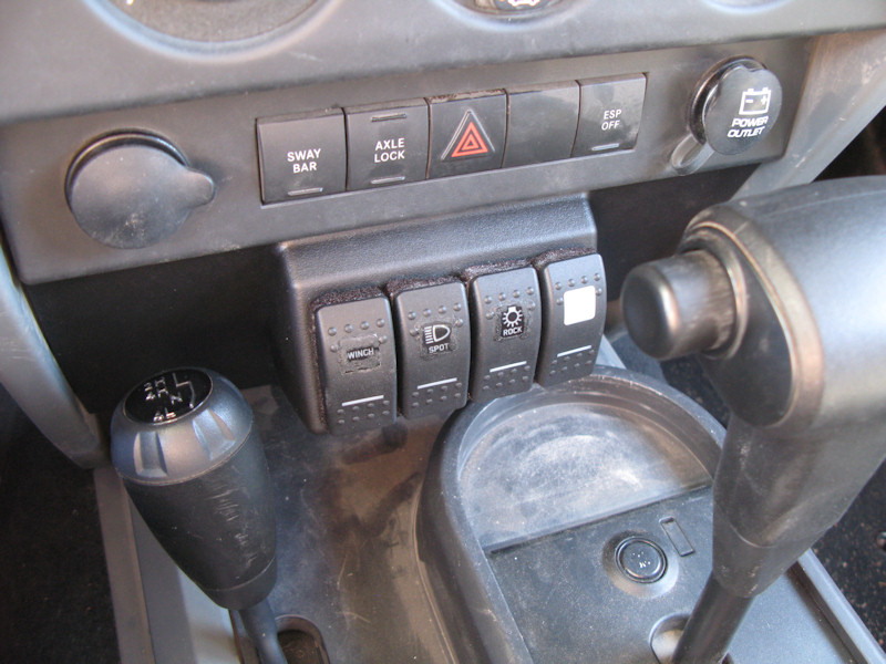
Finished shots:The switches in the daylight. As expected the labels aren't as easy to read as the stock switches, but they're OK. The paint/gunk that I globed on the edge of the labels is clearly visible in the picture, but not as clear in person:
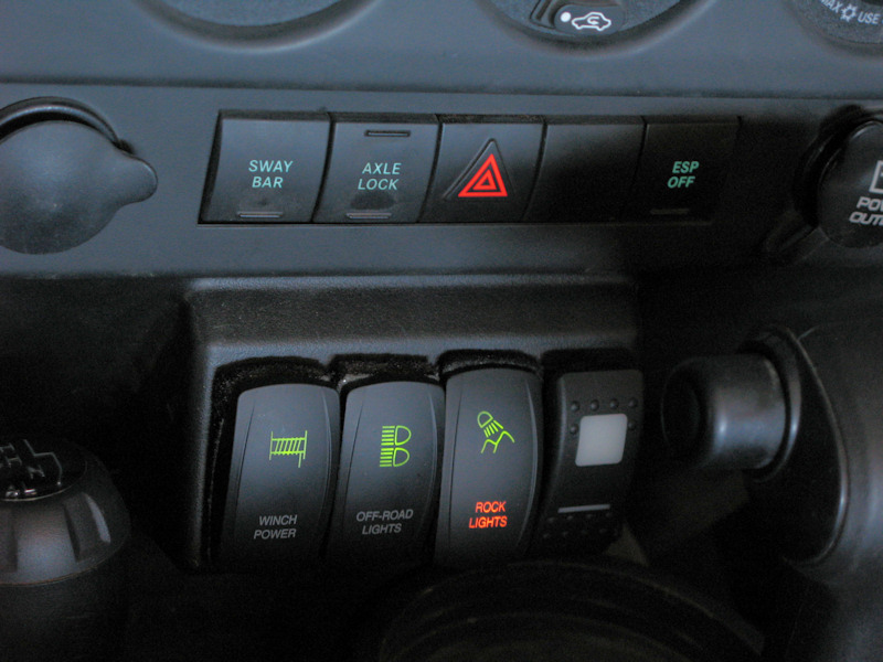
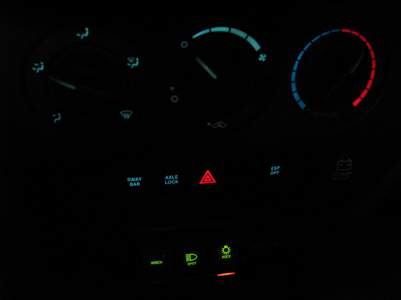
The switches at night with the Rock Lights turned on - clearly visible:
The new switches at night with the Rock Lights turned on - clearly visible:
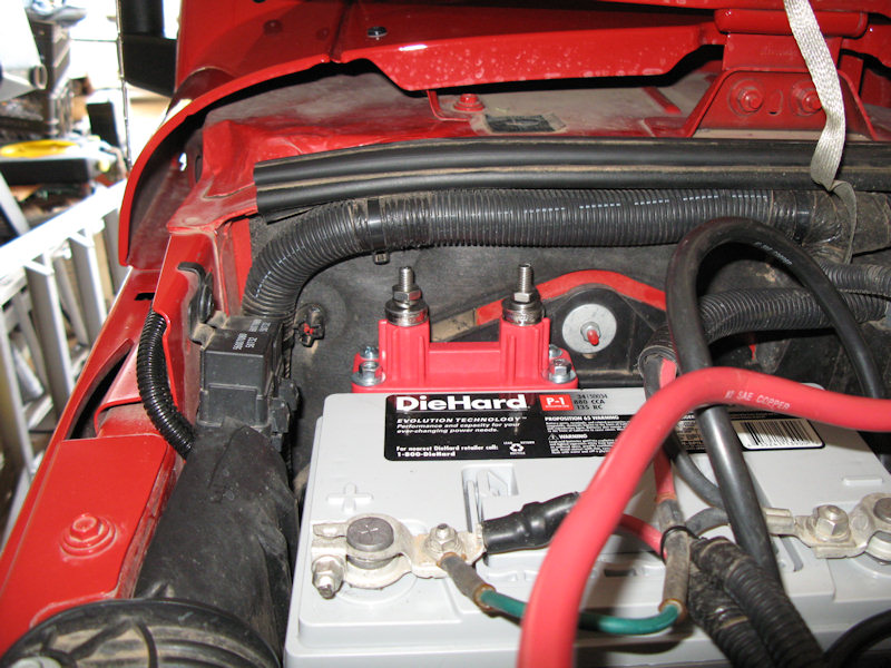
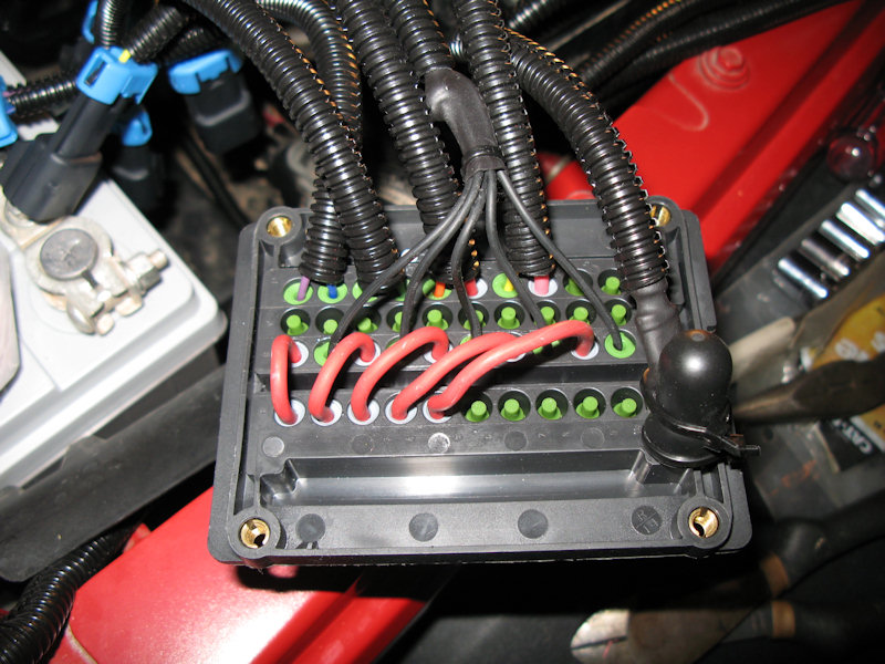
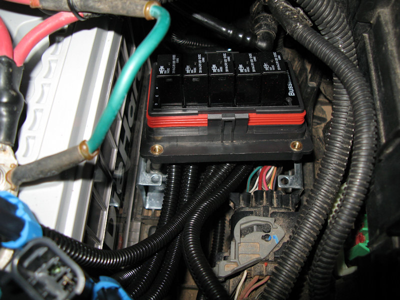
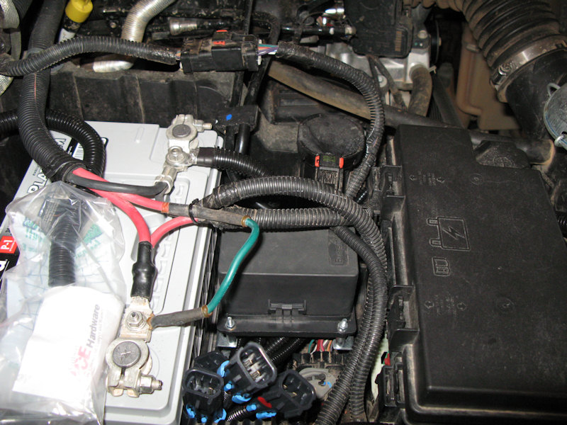
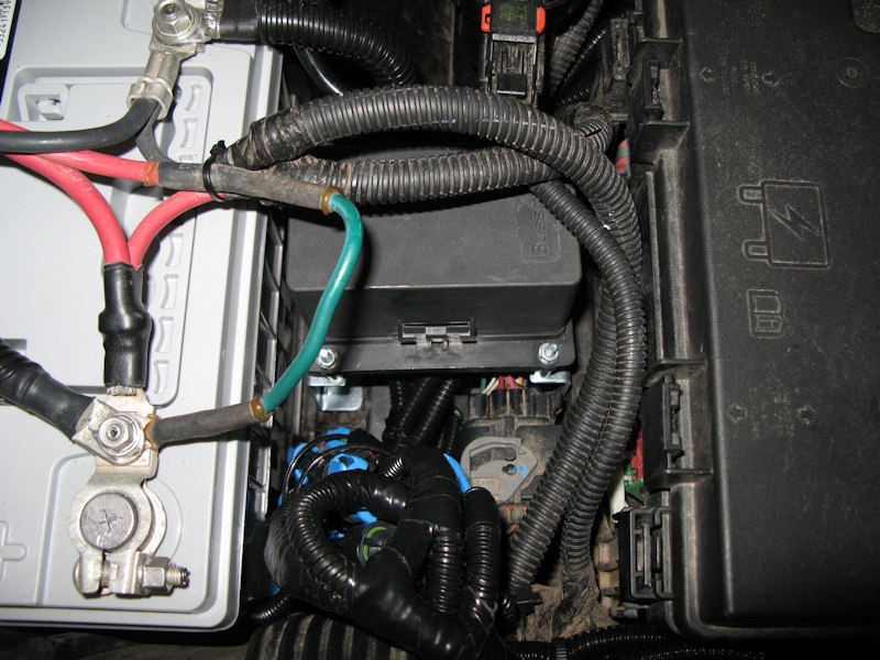
The main fuse in the background, wiring loom from the switches on the left, the new wiring bundle in the lower left, and the RTMR Panel in the lower center:
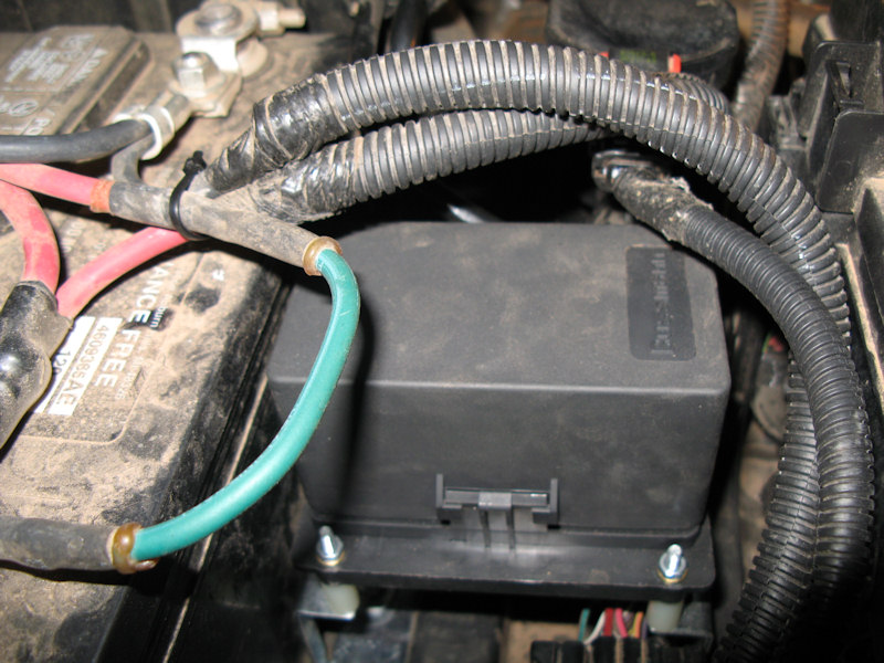
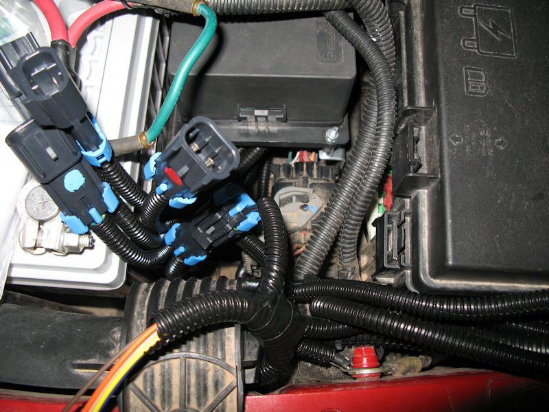
Another view of the RTMR Panel and wire bundle:
The winch relay:
If you have any questions or comments about this page click here to send email.Last modified: March 16, 2012 06:42:02 PM |